
I am trying to calculate/meter the total load I am showing the pickups, but I'm a bit confused. I have a few mods in there to alter the sound of the pickup. The pot is 500k and wired with hot lead to lug 1, lug 2 is output and lug 3 is bent back and soldered to the base. I have 333k resistor and 1000pF cap between lug 1 and lug 2. I also have a 1M resistor between lug 1 and lug 3. I am trying to find out what the total resistive load is that the pickup is seeing.
To sum up. Start with 500k resistance, add 333k, counter with 1M in parallel.
I'd assume it to be somewhere between 333k and 500k, more specifically 454.45k, but my meter is showing a steady 5.11k between lug 1 and lug 3. I have tried reading from lug 2 to lug 3 as well, same results. I've also tried metering the pickup hot to the pickup cold wire, still the same. These readings are nowhere near what I would expect to see. Need a second opinion on what is going on here thanks.
Comments
Member for
17 years 10 monthsI am going to be a bit coy on this one....I am not trying to be
I am going to be a bit coy on this one....I am not trying to be offessive.....I do this mainly to get you thinking about what your learning in school....
What is in parallel with the volume pot in the circuit?
Now what is the formula for parallel impedances?
Draw the schematic, and think about it.....
Member for
15 years 11 monthsAs far as I know the only thing in parallel is the 1M resistor,
As far as I know the only thing in parallel is the 1M resistor, which would act against the pot to give it 333k resistance. Right?
Member for
17 years 10 monthsI think your forgeting something else in the circuit....nudge nu
I think your forgeting something else in the circuit....nudge nudge
Plus you need to draw out the circuit.
Member for
15 years 11 monthsWell, the pickup is in parallel, is that what you are getting at
Well, the pickup is in parallel, is that what you are getting at? The resistor/cap combo are parallel too I think, but not to the pot, they're parallel to the input/output. So not really the same thing I guess, as you said specifically the 'pot' itself.
Member for
19 yearsLink is giving you very good clues... Question 1, what do you
Link is giving you very good clues...
Question 1, what do you think the DC resistance of the pick up is?
Question 2, what is the DC resistance of any resistance in series with a capacitor?
Member for
17 years 10 monthsGuitarfreak you're getting there, Draw the circuit... MrEase is
Guitarfreak you're getting there, Draw the circuit... MrEase is making it easy for you ;)
Member for
15 years 11 monthsHere, I drew this up in a matter of minutes. Wasn't really sure
Here, I drew this up in a matter of minutes. Wasn't really sure where to put the 1M resistor to fit the schematic, but I am almost positive that it is incorrect. I made it red because I wasn't sure.
Attached files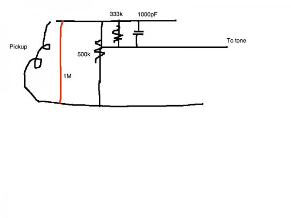
Member for
23 yearsWhat you have here is a parallel circuitry of the pickup, 1 MOhm
What you have here is a parallel circuitry of the pickup, 1 MOhm, 500 kOhm, 333 kOhm and what ever the resistance of the tone pot to the lower lead ( of which you did not say if it is ground or anything else...).
Not to forget that the 1000 pF and the tone pot build a parallel curcuit to the same electric potential of the lower wire, as well.
Now, you must also consider that Ohmic load is not the same then impedance..(inductive & capacitive reactance). On high frequencies a condenser has low resistance (with DC it has infinit resistance) and a choke or coil (with DC almost close to a short circuit ) have high resistance. Pure Ohmic resistors stay pretty close to their value widely independent from the frequencies. This is different in the MHz and GHz area, though..Not interesting, here.
You find all necessary formulas in the internet... usually it takes a few years of apprenticeship to understand and handle this math. Just start with Ohm's law... that one is easy... More complicated it gets with the effects of alternating current and those passive components.
M2c..
Big K
Member for
17 years 10 monthsyour circuit is not complete, its a good start but you need to i
your circuit is not complete, its a good start but you need to include everything in the current loop in order to see why your meter reads what it does. Although with all the hints given I am sure you can guess the main culprit that is lowering the impedance already.
Member for
15 years 11 monthsLink555, post: 352242 wrote: your circuit is not complete, its a
Really I'd love to say that I could guess, but The engineering class I took didn't go much further into the science than 'what is a capacitor' 'what is a transistor' and the teacher was a total lunkhead, couldn't even follow the text himself. His explanations and answers to questions were more confusing than the questions themselves. I didn't learn much unfortunately. All that I have learned has been trial and error or through internet chat sessions like this. My knowledge of the basics and fundamentals is lacking I see now. I really have no idea :frown:
I mean I know that the 1M resistor across the pot is supposed to lower the impedance that the pickup sees, but not THAT much. You all seem to be implying something else in the circuit downstream is causing this and there have been a few references to the tone pot, but really it's just not clicking. Unfortunately my engineering education hasn't taught me anything that deep yet

Are you saying that since there is parallel resistance later in the circuit that the earlier stuff doesn't matter as much as the later stuff? Plus, I thought a guitar's tone knob wasn't as simple as a resistor-cap filter even though I think someone here mentions it as such. Or was that in reference to the volume mod on the volume pot? Or the volume pot acting as the resistor and the tone pot acting as the 'cap'?
Member for
15 years 11 monthsAre you saying that the volume pot is showing the resistance to
Are you saying that the volume pot is showing the resistance to the output while the tone pot is showing resistance to ground? Makes sense, but even so metering lug 1 with respect to lug 2 should show the full pot's resistance shouldn't it? Where else is the resistance going? It doesn't just disappear?
Member for
17 years 10 monthsYour missing the most important part of the circuit in your ques
Your missing the most important part of the circuit in your questions.....Not trying to be a pain, but in my opinion the only way you learn is by working through it yourself..
Now that said.....Mr Ease asked what is the impedance of the Pickups......hint hint
Member for
17 years 10 monthsOh and on your circuit draw it from pickup to guitar jack, map o
Oh and on your circuit draw it from pickup to guitar jack, map out every part, switches, pick ups,caps resistors....etc
Member for
15 years 11 monthsDid my best. How did I do? Attached files
Did my best. How did I do?
Attached files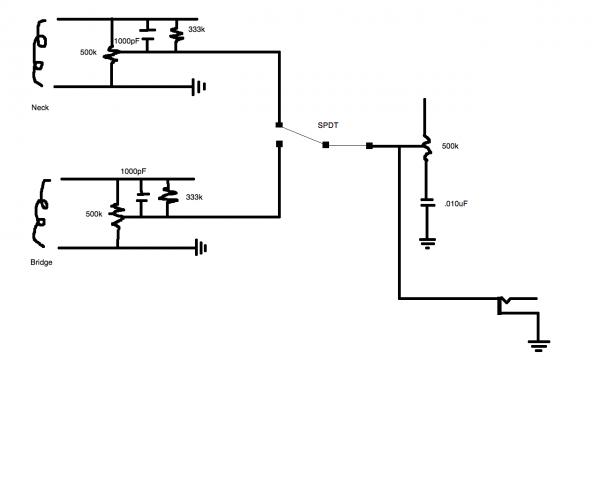
Member for
19 yearsThe circuit's fine. If you now try to answer the two questions
The circuit's fine. If you now try to answer the two questions I posted ages ago you should have all your answers!
Member for
19 yearsGuitarfreak, post: 352249 wrote: You all seem to be implying s
Not me... I'd suggest going as far "upstream" as you can!
It doesn't matter where it is (remember Kirchoff's law from your other thread?), what is important is the individual DC resistance of every element in the circuit. A big clue will be to vary the volume pot and see if that affects your resistance reading. How can that reading of 5.11k possibly occur - there is nothing wrong with that reading BTW.
I'm trying to work with Link555 here as if we just tell you (which we are getting ever closer to) then you will not be thinking it through for yourself and your learning will be limited.
Member for
15 years 11 monthsIs the 5.11k a reading of the pickup itself then? I've actually
Is the 5.11k a reading of the pickup itself then? I've actually tried varying the pot too. Full up and down shows 5.11k and it maxes somewhere in the middle at around ~14k.
Member for
19 yearsClose but not quite! The reading of 5.11k is ALL the resistance
Close but not quite! The reading of 5.11k is ALL the resistances in parallel so the pick up itself is somewhat over 5.11k as there are other resistors in circuit. This is evidenced by the reading rising to 14k (although that sounds a tad high for many pickups). What is clear is that the lowest resistance around is the pickup as this is clearly dominating the reading you are getting. The only way to measure the total load on the pickup is to disconnect the pickup and then measure what is left. This is hardly worthwhile though as you already know the circuit and calculation should be quite adequate. Knowing all the other values actually enables you to calculate the pickup resistance directly. Now there's another exercise for you! :<)
Member for
19 yearsBTW with the circuit as you have drawn it, the minimum resistanc
BTW with the circuit as you have drawn it, the minimum resistance should occur with the pot at minimum and the maximum when the pot is at maximum. There should be no mid range peak in resistance. I notice that your 1 meg resistors have disappeared too!
I suspect that either your circuit is wrong or your measurements are based on the information you have given.
Member for
15 years 11 monthsMrEase, post: 352301 wrote: BTW with the circuit as you have dra
Yeah, like I said I have no idea how to properly notate the 1M resistors within the schematic so I omitted them.
Member for
19 yearsFrom your original description the circuit you did with the 1 me
From your original description the circuit you did with the 1 meg in parallel with the pot was correct. Either way you should not get an impedance peak at the mid volume position.
Member for
15 years 11 monthsA few things on my mind: While your analysis of the reading bei
A few things on my mind:
While your analysis of the reading being a combination of all resistances in parallel, the tone knob still reads ~500k.
The 1M notation I posted first seems like it is wrong because that would imply that the 1M is there to show more parallel resistance to the circuit and get a brighter signal, while in actuality its function is to darken the signal by working against the pot resistance to lower the pot value.
Member for
19 yearsGuitarfreak, post: 352306 wrote: A few things on my mind: While
I very much doubt that! Either your circuit is wrong or you are measuring in the wrong place. EDIT: Woops, see the next post!
Resistors in parallel have a resistance LOWER than the lowest valued resistor, therefore there is MORE load on the pickup with the 1 meg in place, ignoring the 333k resistor for now, the pickup load would be 500k without the 1 meg and 333k with it. This should indeed "darken" the sound.
While we are doing our best to help you here, there is no doubt that you are struggling with the basics of electronic networks. You really need to find some good tutorial books or find another course with a tutor who is actually going to teach you something worthwhile.... I think there is only so much support we (or at least I) can give on this forum - we (I) have to earn a crust as well...
Member for
19 yearsSorry, in my first quote I mistook the tone pot for the volume p
Sorry, in my first quote I mistook the tone pot for the volume pot! The thing there is that the tone pot has a capacitor in series with it and that will look like an open circuit at DC hence the pot value has nothing effective at DC in parallel with it and therefore you will measure just the pot value.
Member for
19 yearsHey, Guitarfreak, I was just browsing thinking of your "basics"
Hey, Guitarfreak,
I was just browsing thinking of your "basics" and came across this site. I think you should find it very useful.
[[url=http://[/URL]="http://www.electron…"]Basic Electronics Tutorials and Revision[/]="http://www.electron…"]Basic Electronics Tutorials and Revision[/]
I had a quick read through and it seems mostly OK although I did have some serious issues with their section on transistors. The author seems to think that transistors are current operated devices which is quite wrong! I have contacted them to point out the error but have no idea if they will take any action. It could be a good pointer to the integrity of the site if they react to such a blooper!
Member for
15 years 11 monthsMrEase, post: 352331 wrote: Hey, Guitarfreak, I was just browsi
Thanks!