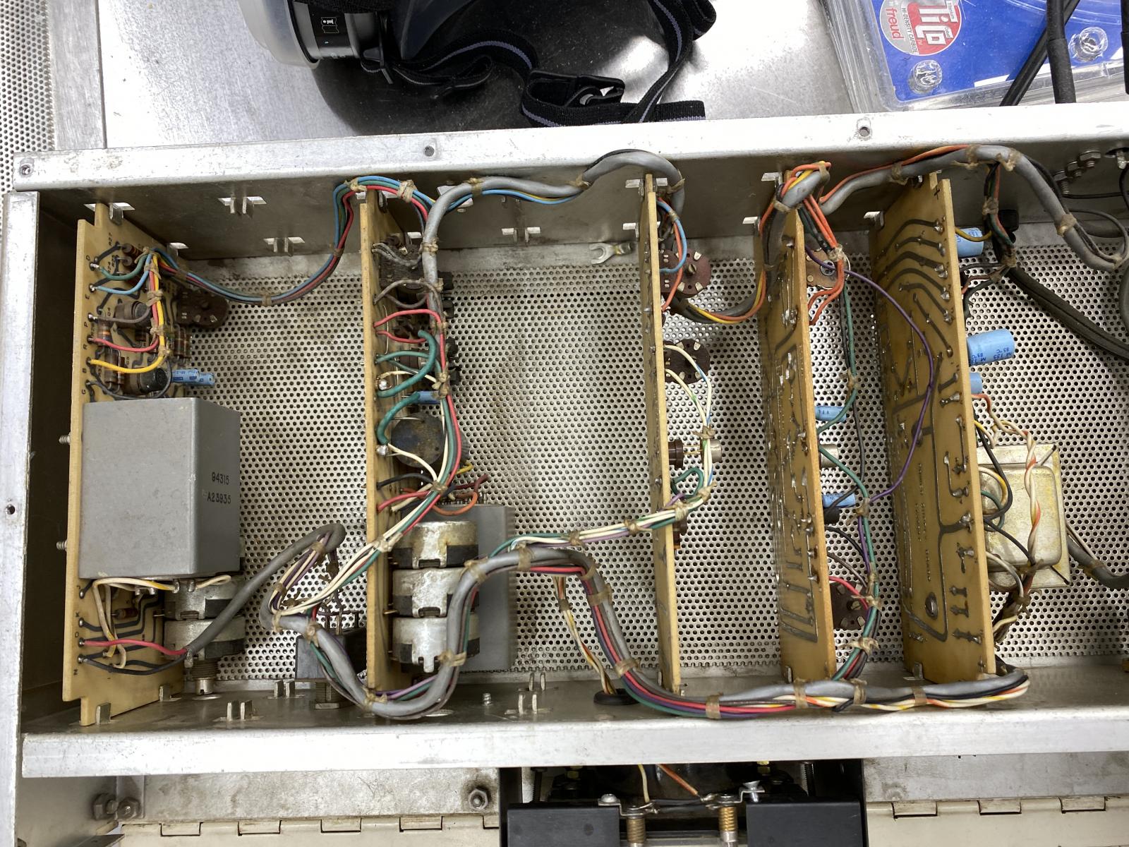
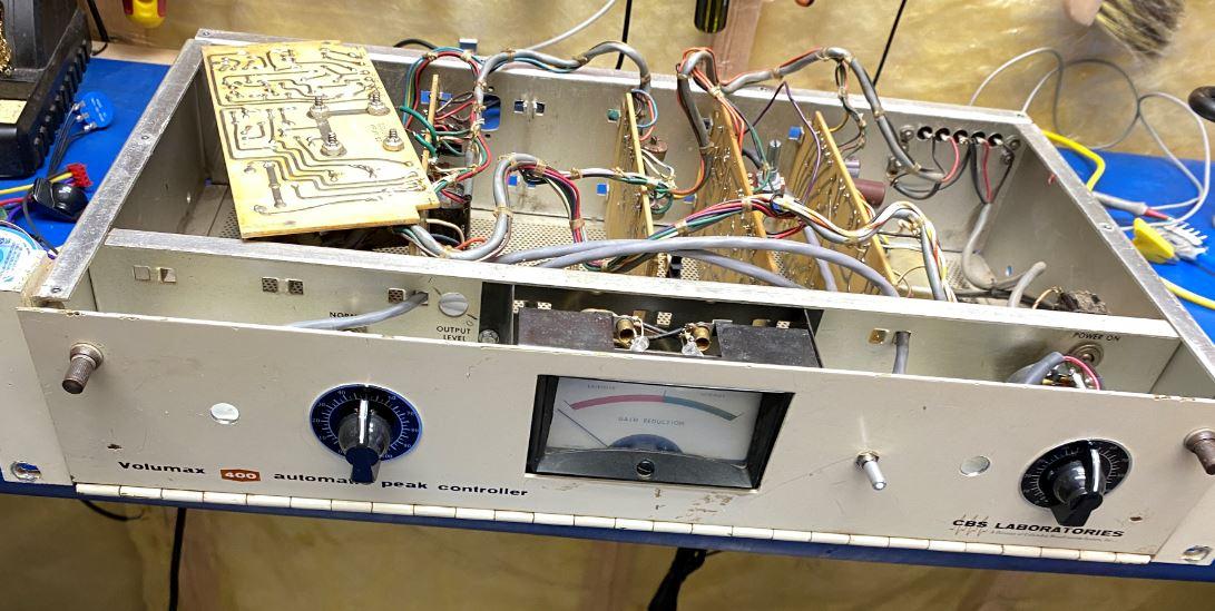
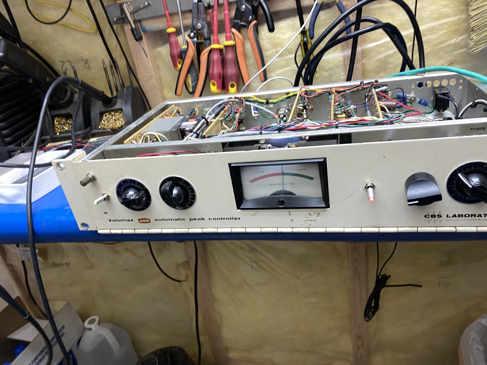
This baby came in for a recap and few mods....Most Maintainable build I think I have ever seen. Its dream to work on.
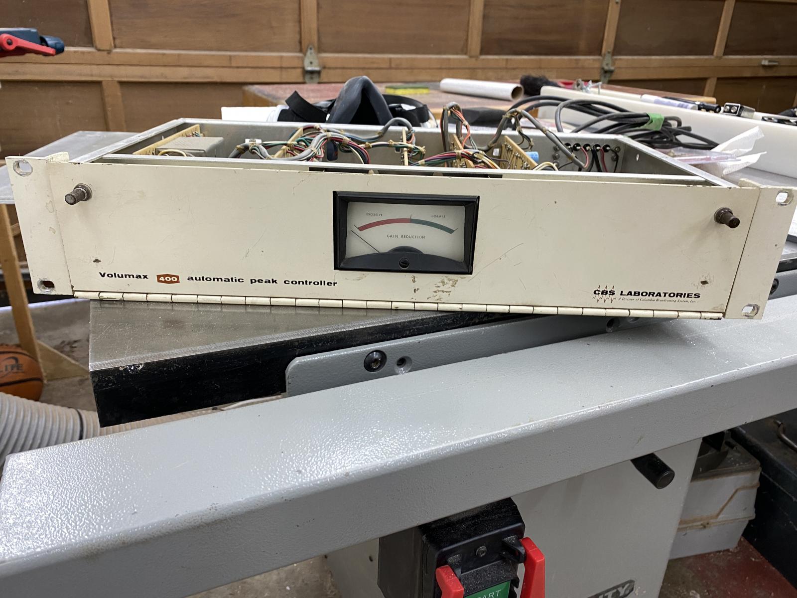
- Document
Attachment Size cbs_am_volumax_model_400_manual.pdf (6.88 MB) 6.88 MB
Comments


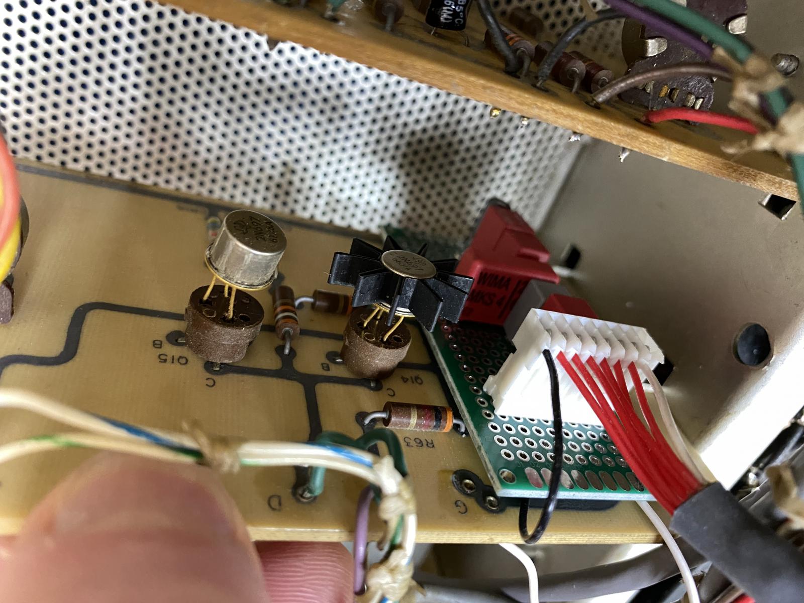
Starting to look at a few things: The balance or ratio&nbs
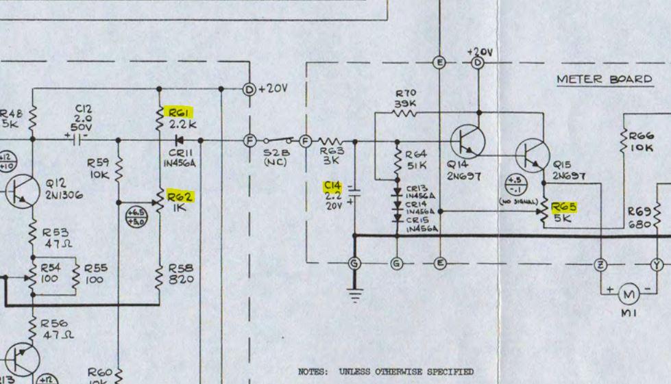
Starting to look at a few things: The balance or ratio between the attack and release times seems to fixed because of the driver and buffer impedances. Its strange how they drove the meter without a separate buffer.
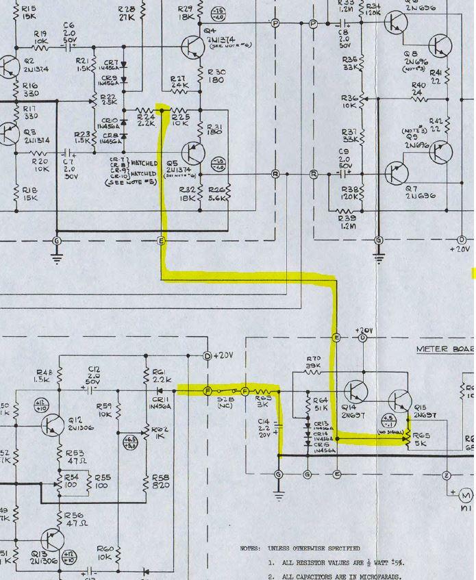
but it looks like I can Vary C14 values to affect both the attack and release times. So maybe a switch with selectable caps. 0u5, 1u,2u2, 4u7,10u something like that....
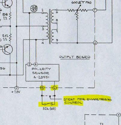
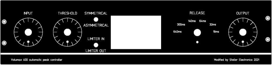
The other thing I want to try is bringing a switch out to the front to switch between symmetrical and asymmetrical side chain detection.
I also want to try add an adjustable threshold control. Right now I am looking at two possible controls. Moving R62 to the front panel and putting a 10k trim pot in for R61. And/Or bringing R65 to front panel. I am not sure which one will work best, as they both will affect the gain.

Other than that I will move the input and output T pads to the front plate, added a grounded power plug, change the VU meter lamps to LED, and recap the unit.
I have now recapped the unit, and started in on the mods.&
I have now recapped the unit, and started in on the mods. I am adding a threshold control. I added 1K pot to the front panel and wired to where the R62 trim pot was.
I changed R61 to a 10k trim rheostat. It gives me a bit more control over the threshold.
I cleaned and lubricated the input and out attenuators, and moved them to the front panel.
Output attenuator Before:
Output attenuator After:

I added a switch to change the side chain signal for symmetrical to Asymmetrical.
I have ordered a SP6T selector switch and plan to change C14 with 6 different values. I will try 0.1uF,0.47uF.1uF,2.2uF,4.7uF and 10uF start and see how the circuit responds.
I also planning to add a switch to remove the side chain signal from the amplifier, to defeat the limiting action.
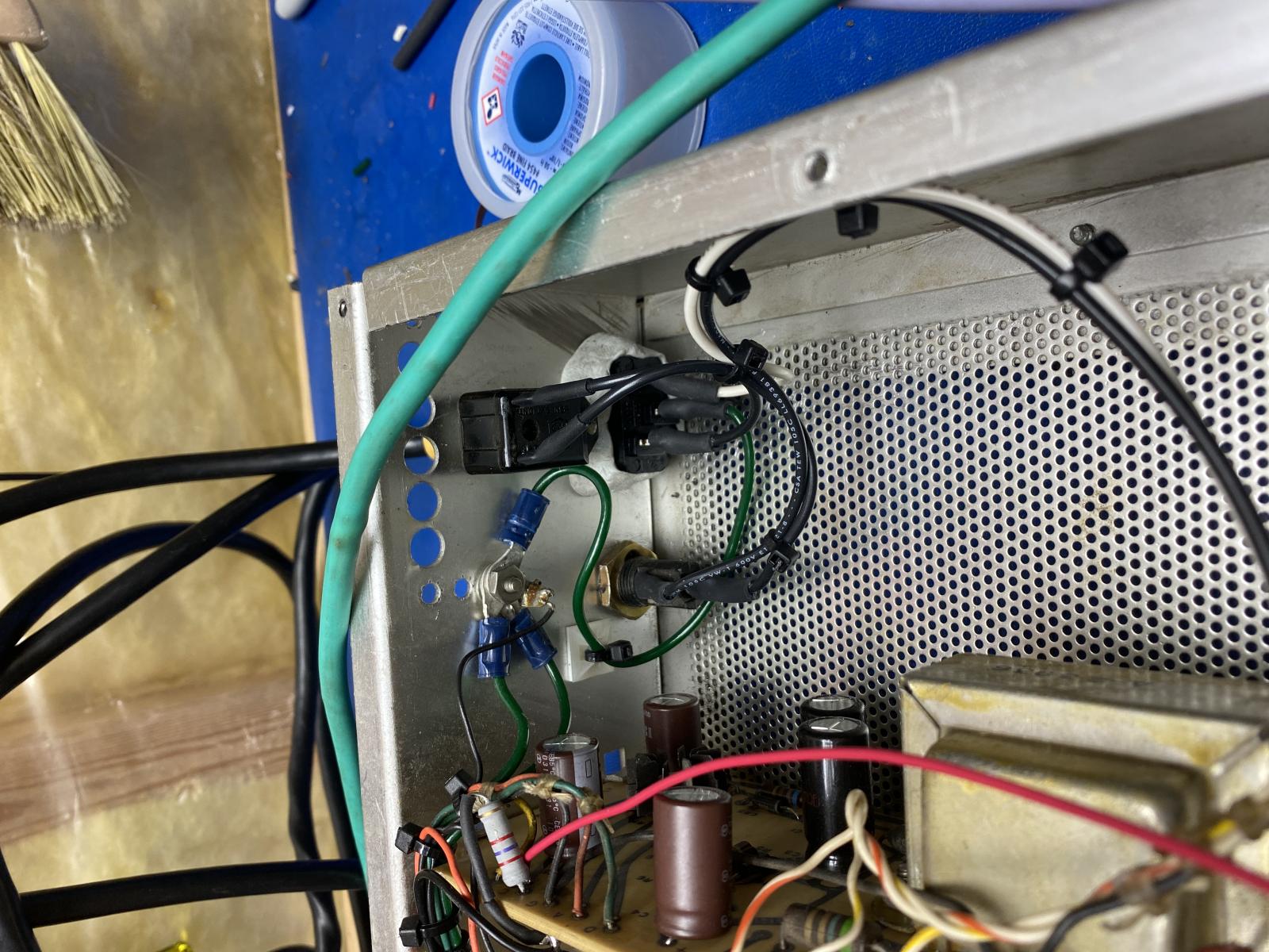
I also still need to remove the input and output terminal block and add two XLR connectors. This will allow to reduce the internal wiring for the input and output signals, which will brings signals directly to their respective cards. Also it will allow me to not have to wire the input signal cable across the signal input 120VAC power input.
The owner is also looking for a new faceplate for this unit as well. To do this I will remove the service hinge and put a new fixed panel on the front. I will move the power switch and fuse to the back panel, as well change the ungrounded power cord to a chassis grounded cord.
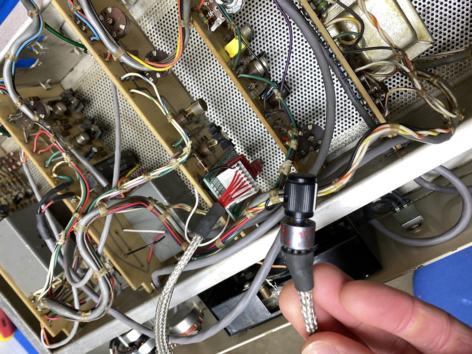
Had time last night to put the new XLRs in. The old line i
Had time last night to put the new XLRs in. The old line input via the terminal strip had an internal cable tied the the AC hot for at lease 8" of cable. The new connections go directly to the their respective cards. I was surprised that this new shorter connection really improved the signal quality, I was not excepting and audible difference.
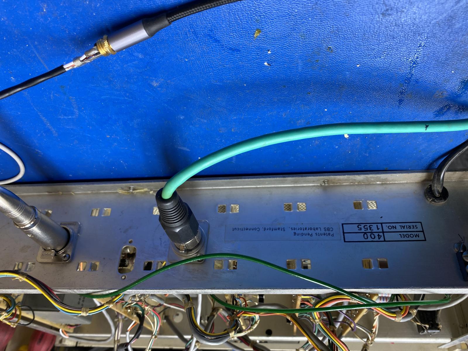
I also star grounded the pin 1 on the xlr connectors.

I'm afraid I can't accept this as the physics means that if you
I got my fresh order of WIMA caps and the SP6T rotary switch yes
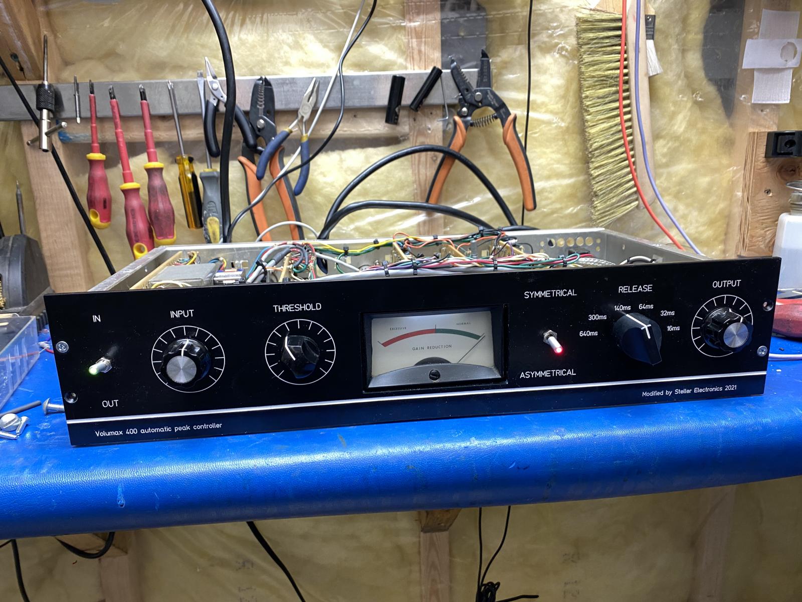
Well let's try this again, My last post got lost in the shuffle.
Well let's try this again, My last post got lost in the shuffle. THe unit is completed now was picked up last night. Its a pretty transparent limiter in the end. If you push it hard it breaks up, in not such a nice way. But if you keep it in the green its pretty useful.
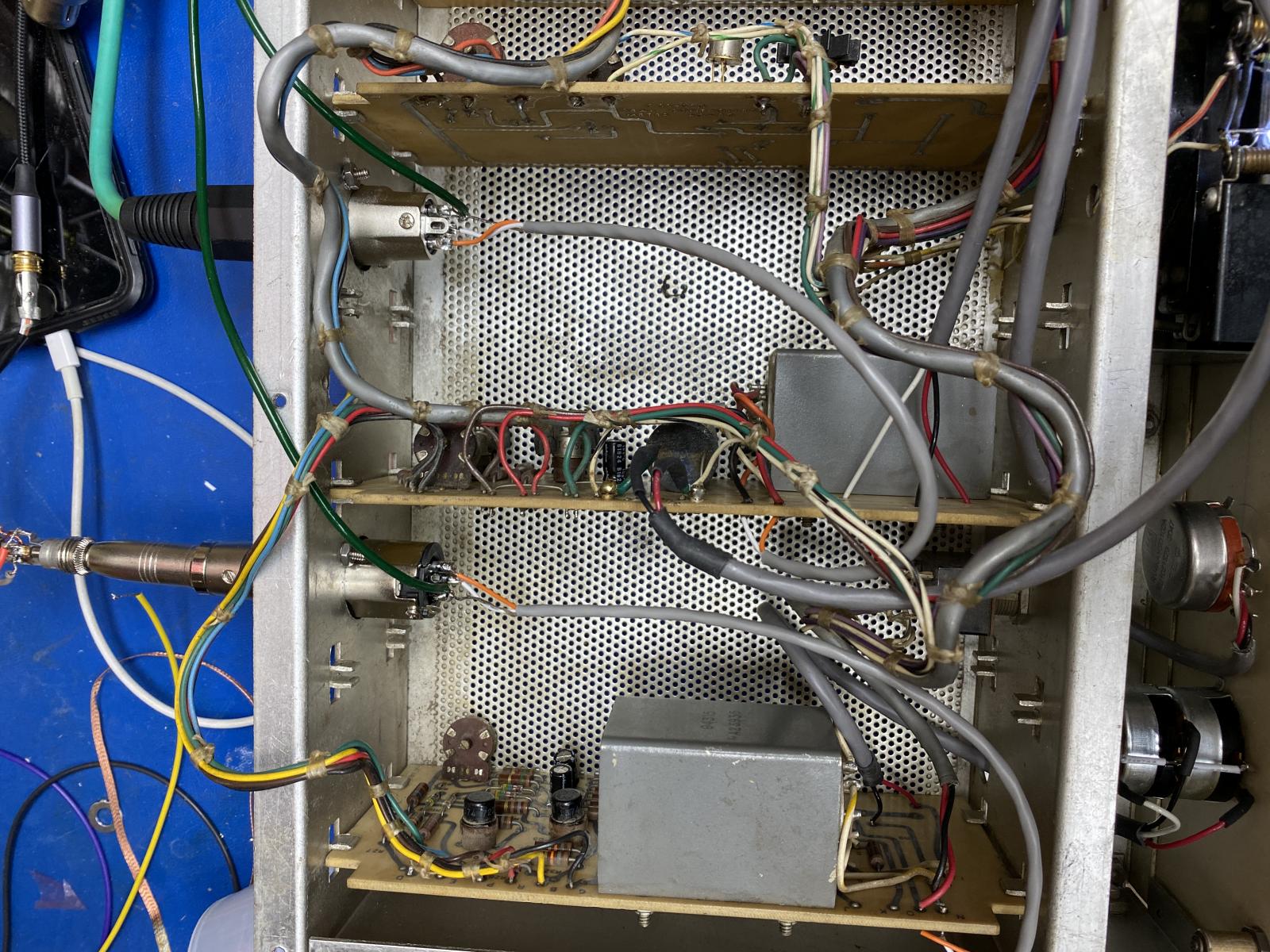
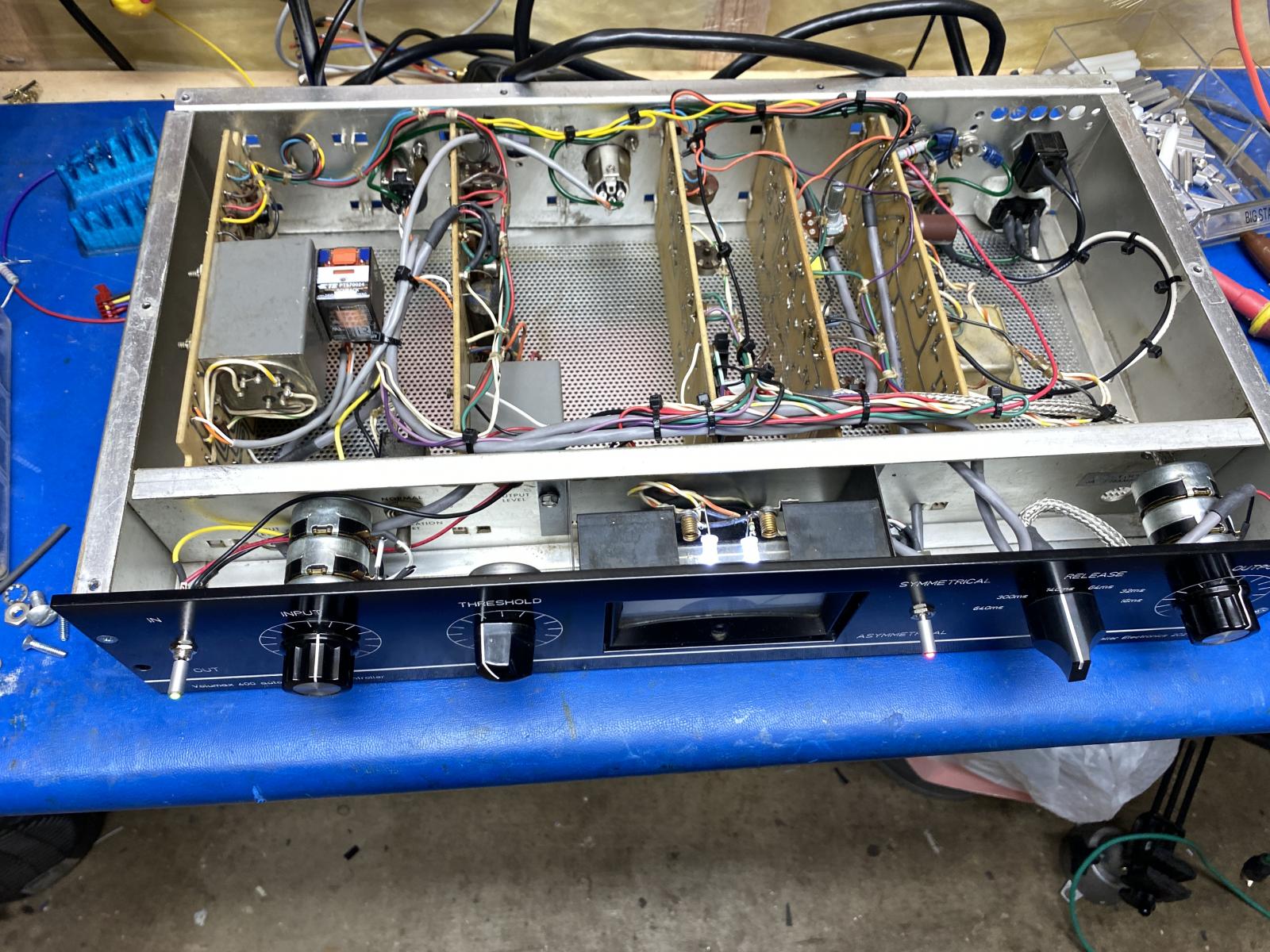
I grounded the chassis and made a star point ground for all the cards. The thick green wires are the new grounds.
I cleaned up the wiring, and tested the unit.
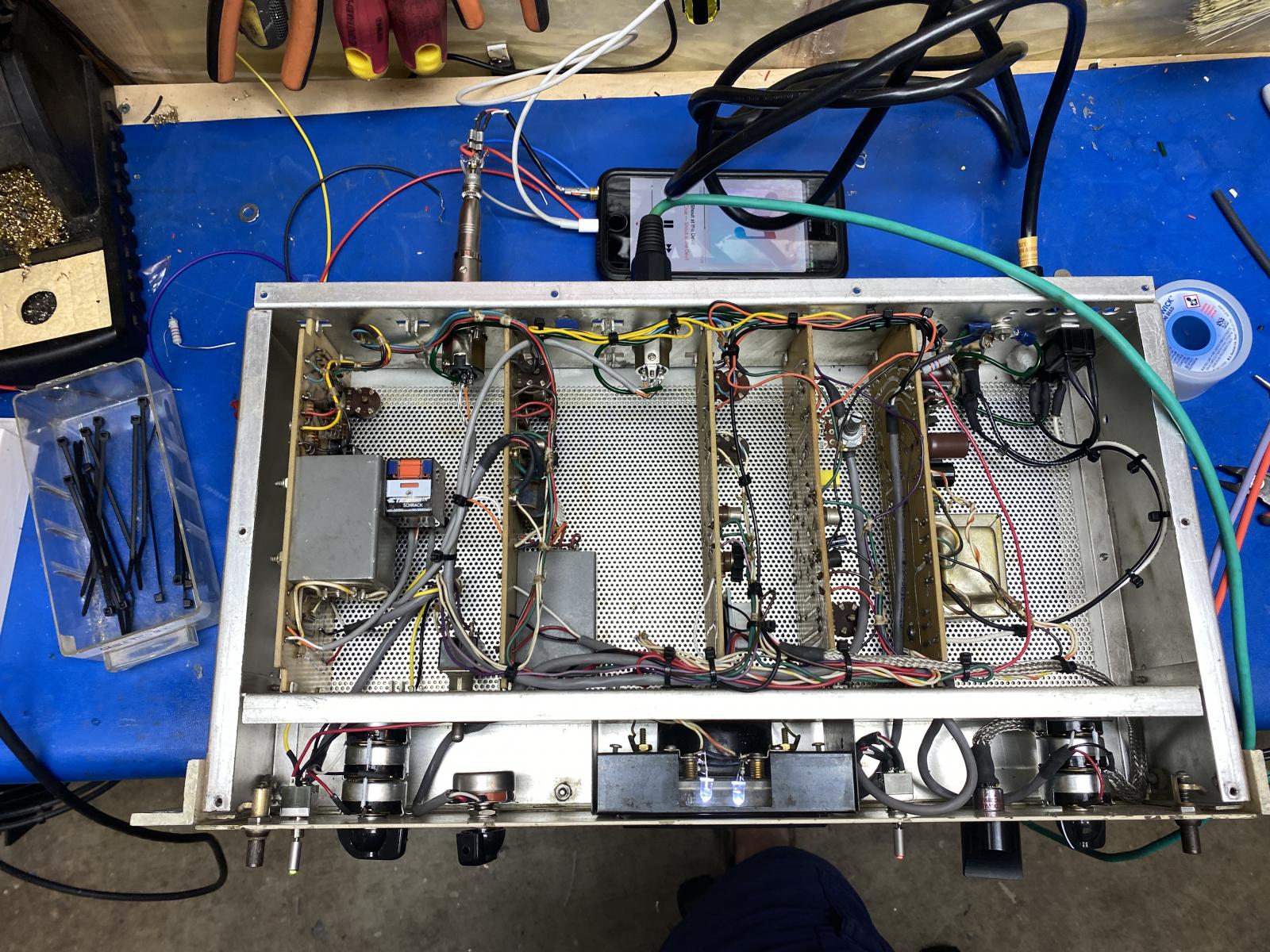
I also added the true bypass relay and switch. I modified the original face plate to allow for some some testing.
Then the new front panel Arrived.


nice! are you modding it with attack / release / threshold and m
nice! are you modding it with attack / release / threshold and make up gain controls?