In for a recap and retube and a few modifications. It’s missing the memory module. so it will need some thinking... Looks like a nice build so far..
Tags
Comments
This post probably got lost in the server restart. As I still ha
This post probably got lost in the server restart. As I still had the email, I've re-posted it.
Link555 replied to a thread you are watching at Pro Audio Community Forums. 09/02/2021, 02:00
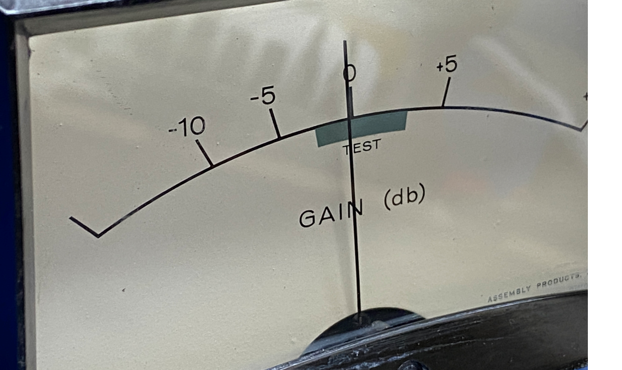
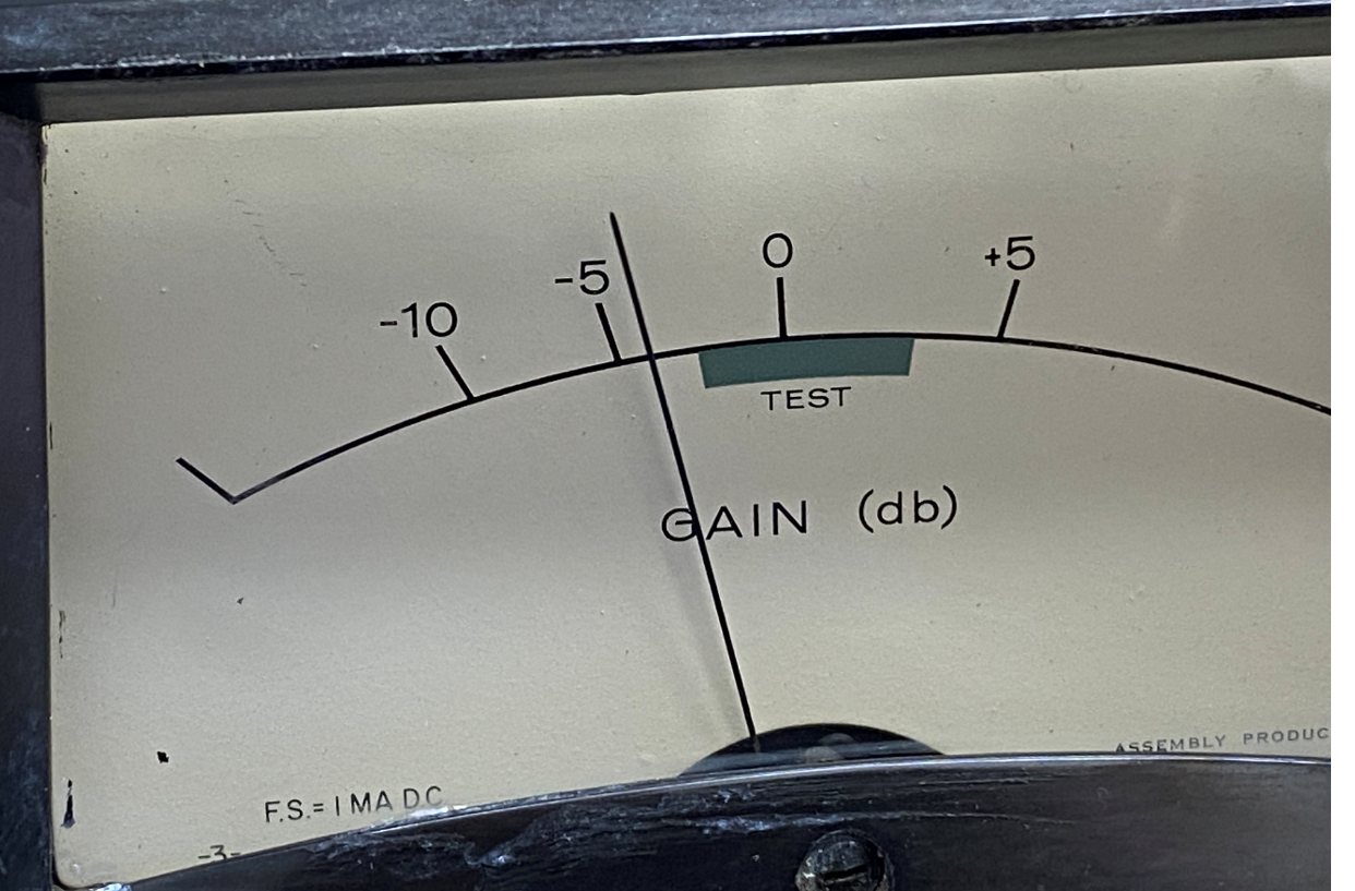
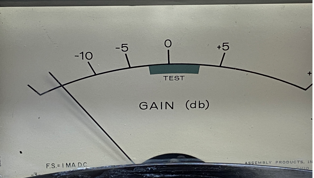
Spent way too much time today tearing the meter movement down today, trying to find where it was binding ever so slightly. There was a small clip on inside binding the needle. Now it is working properly. now I can Start to tune the meter, I am wondering if I should move the meter to read the current through v6, since it’s only a gain reduction meter? As it is now it is reading hot....
I don't think it's worth changing the meter to read the current
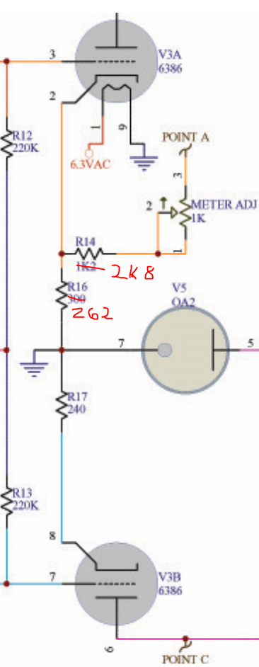
I don't think it's worth changing the meter to read the current through V6 (the 6AL5 dual diode), as in normal operation you would only get short pulses of current at the negative waveform peaks. You need the meter to represent either the compression control voltage or the current through the vari-mu triodes (which is what it does at present). Unless you fancy re-drawing the scale on the meter panel, it would be best to stick with the triode current as given by the voltage on the cathode resistor(s), and patching other resistors in to bring it into range if necessary.
I thought the original design was a bit lazy in the metering connection. I would have made the cathode resistors the same value, and then had something like a pair of equal resistors in series linking the cathodes, and the meter current taken from the centre-point to ground, possibly with a calibration rheostat in series with the meter. This would have the advantage of removing much of the signal a.c. through the meter. It would need careful choice of splitter resistors, as they would introduce noticable negative feedback if they were too low. You have to be very careful about using negative feedback in a controlled variable-gain circuit!
Do you know what the FS meter current is?
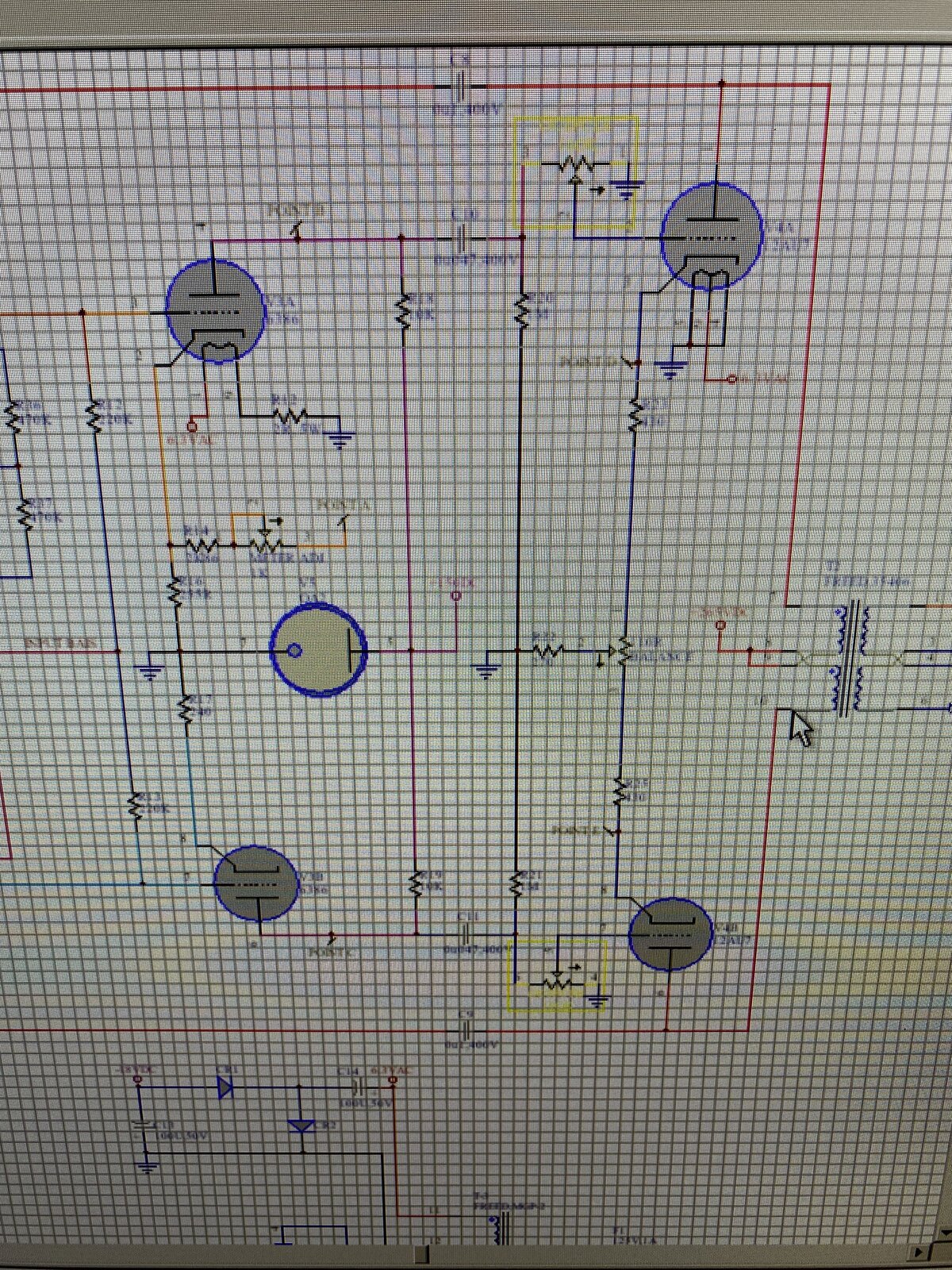
Testing a link to PDF of the updated schematic: https://smallpd
Testing a link to PDF of the updated schematic:
Does this work?
Boswell, post: 467351, member: 29034 wrote: I don't think it's
Boswell, post: 467351, member: 29034 wrote:
I don't think it's worth changing the meter to read the current through V6 (the 6AL5 dual diode), as in normal operation you would only get short pulses of current at the negative waveform peaks. You need the meter to represent either the compression control voltage or the current through the vari-mu triodes (which is what it does at present). Unless you fancy re-drawing the scale on the meter panel, it would be best to stick with the triode current as given by the voltage on the cathode resistor(s), and patching other resistors in to bring it into range if necessary.I thought the original design was a bit lazy in the metering connection. I would have made the cathode resistors the same value, and then had something like a pair of equal resistors in series linking the cathodes, and the meter current taken from the centre-point to ground, possibly with a calibration rheostat in series with the meter. This would have the advantage of removing much of the signal a.c. through the meter. It would need careful choice of splitter resistors, as they would introduce noticable negative feedback if they were too low. You have to be very careful about using negative feedback in a controlled variable-gain circuit!
Do you know what the FS meter current is?
Thanks Boswell, I had it hooked up to the DC power supply yesterday through a multiturn pot to try and figure out what was binding it, but I did not measure it. I can easily do it tonight. I want to recheck the threshold connections tonight because the control has little to no effect.
Boswell, post: 467351, member: 29034 wrote: I don't think it's
Boswell, post: 467351, member: 29034 wrote:
I don't think it's worth changing the meter to read the current through V6 (the 6AL5 dual diode), as in normal operation you would only get short pulses of current at the negative waveform peaks. You need the meter to represent either the compression control voltage or the current through the vari-mu triodes (which is what it does at present). Unless you fancy re-drawing the scale on the meter panel, it would be best to stick with the triode current as given by the voltage on the cathode resistor(s), and patching other resistors in to bring it into range if necessary.I thought the original design was a bit lazy in the metering connection. I would have made the cathode resistors the same value, and then had something like a pair of equal resistors in series linking the cathodes, and the meter current taken from the centre-point to ground, possibly with a calibration rheostat in series with the meter. This would have the advantage of removing much of the signal a.c. through the meter. It would need careful choice of splitter resistors, as they would introduce noticable negative feedback if they were too low. You have to be very careful about using negative feedback in a controlled variable-gain circuit!
Do you know what the FS meter current is?
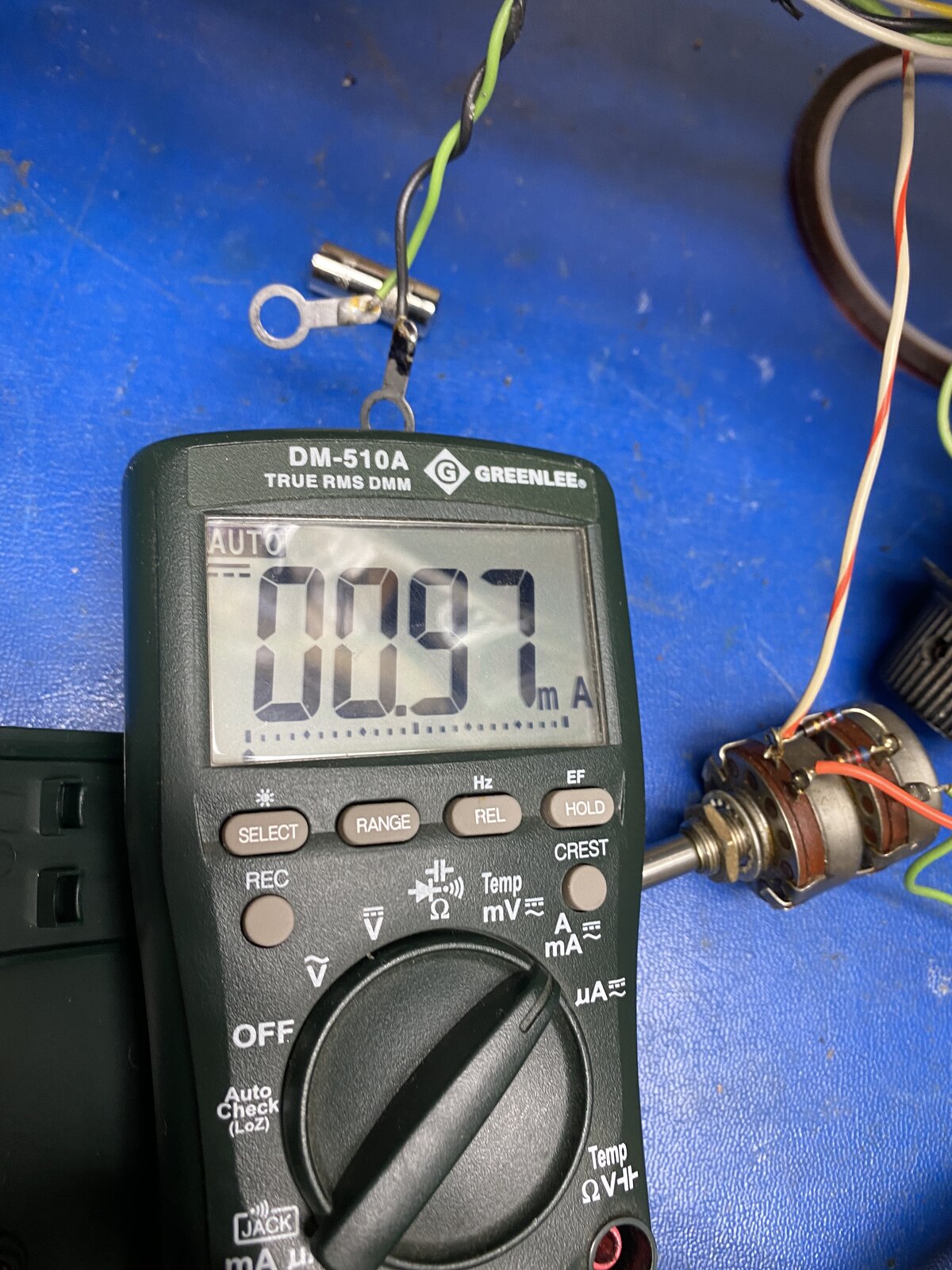
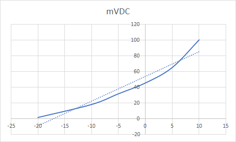
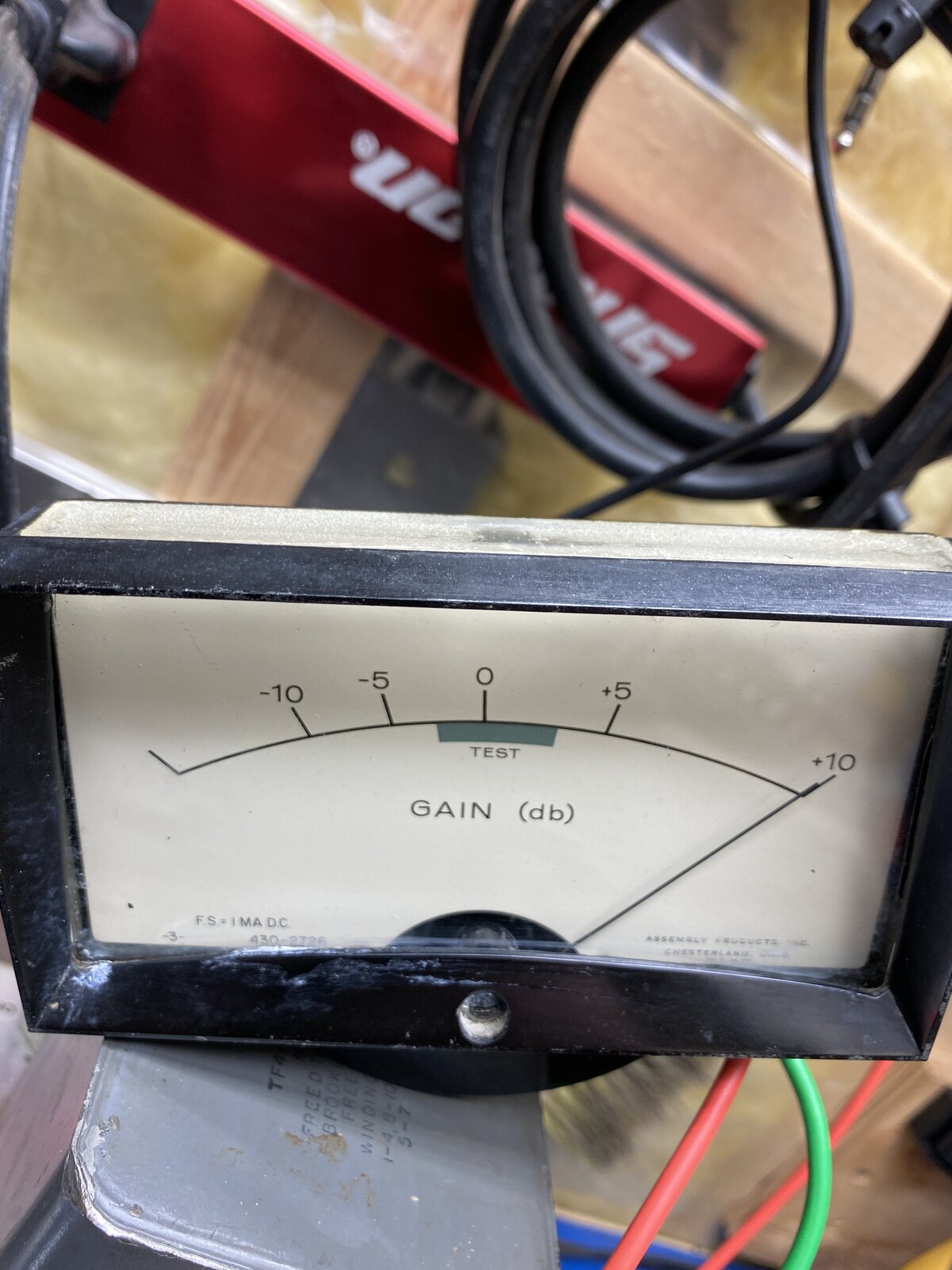
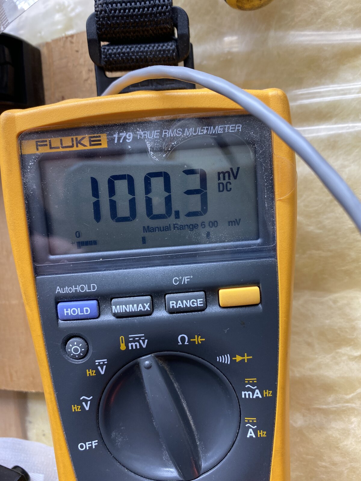
Just did a few quick measurement full scale is 100mvdc at 1ma. Not a very linear meter.
Boswell, post: 467348, member: 29034 wrote: It doesn't look as
Boswell, post: 467348, member: 29034 wrote:
It doesn't look as though the Output Level control appears on the JLM mod schematic. How was it connected? Does it actually scale the signal or does it tinker with the compression control voltage?When reducing the level, going through a zero and then the polarity reversing is an effect you can get with vari-mu valves (or with solid-state devices) when they are used in a fully differential circuit. If there's an imbalance in the two halves of the 6386, the triode in the +ve leg may cut off before the one in the -ve leg, so the small remaining signal arrives inverted at the output. In an earlier post I mentioned that 6386s with tested matching of the two halves were difficult to obtain, and the corollary of that could be that the devices that are available are not particularly well matched for cut-off. Sometimes this can be first-order corrected by resistor scaling the grid volts on one of the triodes, but that can upset the large-signal a.c. and the standing d.c. balance as well.
I am not sure this related to the imbalance of the 6386 triodes....The output pot is mod someone else threw in. I wasn't sure about it so I left it off my schematic redraw until I could prove it out. It uses a Allen bradley dual rheostat (4 pin model).
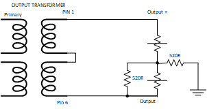
The schematic looks like this... I think this might explain the polarity flip...
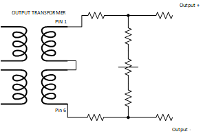
I am thinking to just replace this with a balanced T pad with pot in the middle.
I've never seen an output level control wired like that! However
I've never seen an output level control wired like that! However, I can't make your diagram match the photo. There seems to be no direct join between the top of one rheostat and the bottom of the other. The connections between the two go only through the 620R resistors.
I think you have to work out what dB range of level adjustment you want on this control, and then devise a configuration using the CW and CCW resistances (plus the corresponding two zeroes) as the end points in your simultaneous equations to get the fixed resistor values.
The only point of a T-pad would be to present a moderately constant resistance (e.g. 600R) to the output transformer. The original configuration may have had that in mind.
It seems from the photo that the variable control is actually a ganged pair of standard 3-terminal pots that have had the opposing end terminals cut off. You can see what would have been the central wiper terminals of the original are in alignment. Weird.
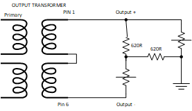
That may represent what is wired on the control, but it still lo
That may represent what is wired on the control, but it still looks too asymmetrical for a balanced output. I don't like the way the upper signal (+?) can be shorted to ground when the control is at one end. Is it possible that either the ground wire actually went to ground through another 620R on the main board, or else the terminal shown as ground is not actually ground? The studio convention in those days was that outputs were either floating or centre-tapped to ground, so the level adjust control should not have had a direct ground connection.
Do you know which points on the control went to the final output socket?
Boswell, post: 467381, member: 29034 wrote: Do you know which
Boswell, post: 467381, member: 29034 wrote:
Do you know which points on the control went to the final output socket?
The point labeled output+ and output - go to the output socket.
Looking closer The ground connection looks like it is switched to ground when the meter is reading the V3 and V4 voltage, otherwise it floats....I think
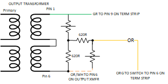
Ok try three... The White and orange wire goes directly to pin
Ok try three...
The White and orange wire goes directly to pin 6 on the output transformer. Another orange/white connection goes to J2 as per the schematic
The Green wire goes to the switch and jumpers directly(not switched) from there to the output connector pin 9 (output+).
And the Orange Wire goes through the first position of the switch A to PIN 6 of the output terminal strip via the RED/YEL wire (Output -)
Was this output level control installed by some previous modifie
Was this output level control installed by some previous modifier rather than being an official CBS add-on? If so, then it could well be a hack job with little regard for symmetry or balance.
I assume you are keen on having some form of output level control, especially now you have given it a place on the new front panel for the unit, but that doesn't have to mean that you must re-use parts that are not particularly suited for the job. Having a pair of variable resistors where one of them goes up as the other goes down does not sound like a good starting point for a balanced variable attenuator.
I've not designed with those transformers, so I don't know how sonically critical it is to keep them with a roughly constant load. Having seen the photos of the environment where this unit will be working, it looks likely that maintaining good balanced interconnecting circuits will be the order of the day, and that there's a high likelihood that the next unit in the chain will have an input transformer. My experience says that there would be less tonal difference from driving a transformer input from a balanced but non-constant impedance such as the wipers of a standard ganged pot than having a variable load on an output transformer. Not that simple, and there may well be compromises that have to be made.
Thanks Boswell, The output pot is not original for sure. Compro
Thanks Boswell, The output pot is not original for sure. Compromises will need to be made, that I am sure. And this unit will likely end up feeding an input transformer, so I will need to do some experimenting to see how the load variation affects the signal. Right now I going remove the output control and focus on the issues with threshold, attack and release.
I know the meter is working reasonably well by itself, butas you point you pointed out the circuit feeding it is problematic. so that will be the second problem to address. First I want to figure why the threshold has seemly no effect.
Boswell, post: 467389, member: 29034 wrote: I agree - one secti
Boswell, post: 467389, member: 29034 wrote:
I agree - one section at a time, at least where they don't interact.
Very true. I went down a rabbit hole last, even after I said I wouldn't.. :)
I started fiddling with the meter series resistor. I got it read correctly by changing R14 to 2k8 and R16 to 262. That allowed the R15 pot to be the center with the meter reading 0.
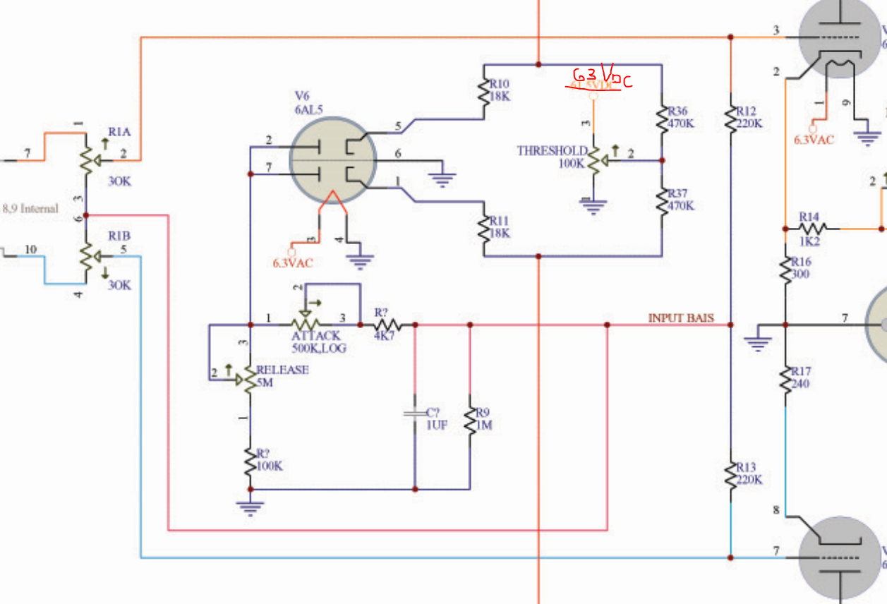
I also played with threshold and noticed that when the wiper is at 100k and ~63VDC is applied to center junction between R36(470k) and R37(470k) there is no gain reduction.
However the gain reduction does not seem to start until the wiper is less than 10k, and the voltage and the junction is less than 6VDC. Because of this the threshold is doing very little for most of its range.
I also noticed that when the wiper is at 0k and 0VDC is applied to the junction, the audible noise in the circuit increases and the meter shows a slight jump in reduction. Might need to add a small resistor to lift the lowest position.
I am still hoping for a wiring error...more playing tonight
Testing the ability to add a PDF file in a post Attache
Testing the ability to add a PDF file in a post
Attached files example4.pdf (189.5 KB)
Ok trying it out... Thanks! Attached files CBS AUDIMA
Ok trying it out... Thanks!
Attached files CBS AUDIMAX II MODS R3.pdf (46.3 KB)
Boswell, post: 467391, member: 29034 wrote: Was this with conti
Boswell, post: 467391, member: 29034 wrote:
Was this with continuous sinewave input, and what input signal level and R1 setting were you using?What were the corresponding generated control voltages (top of the 1uF cap)?
I did not get as much time as I could have used last night but I did manage to run the sine wave through the unit and observe the voltage on the 1uf cap with respect to common.
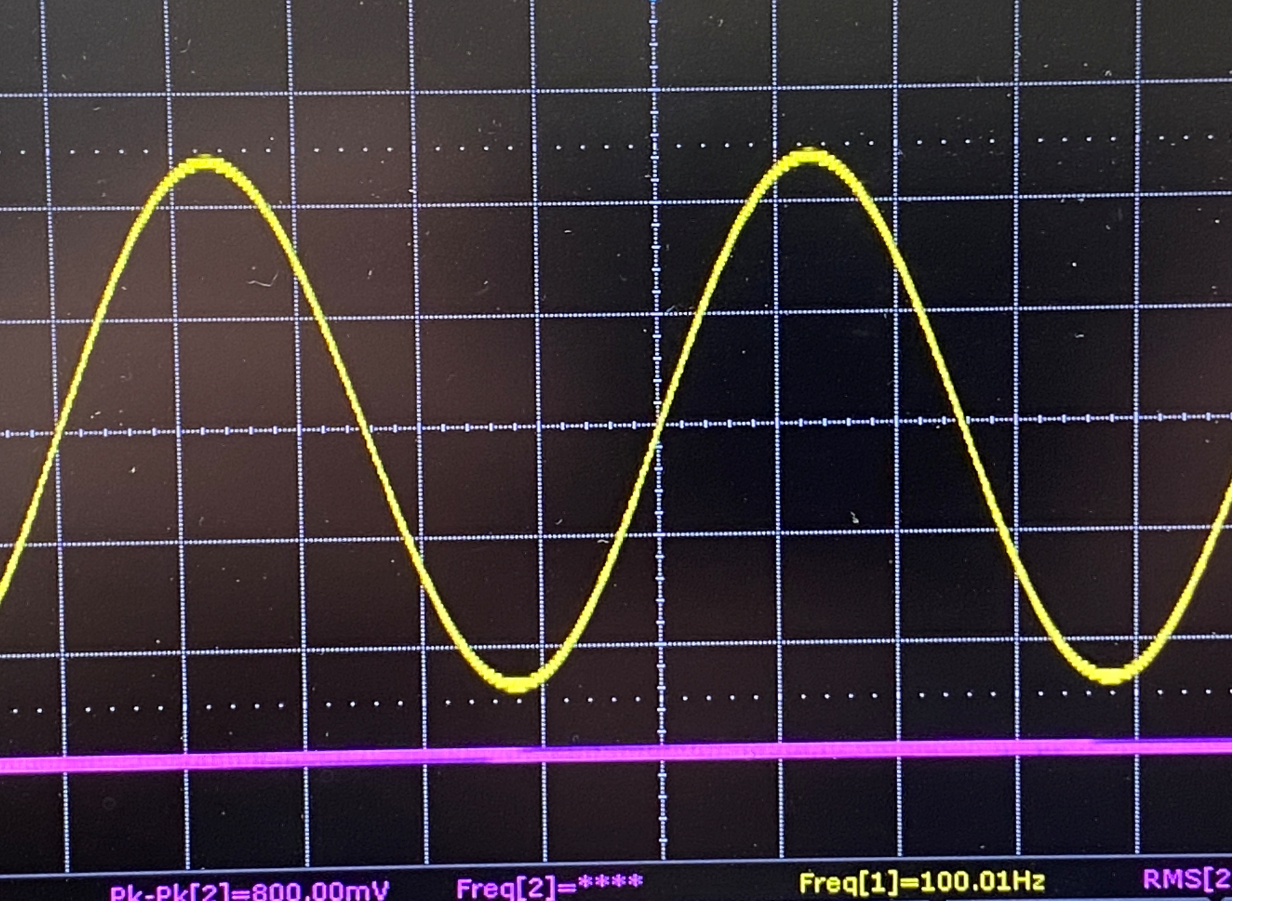
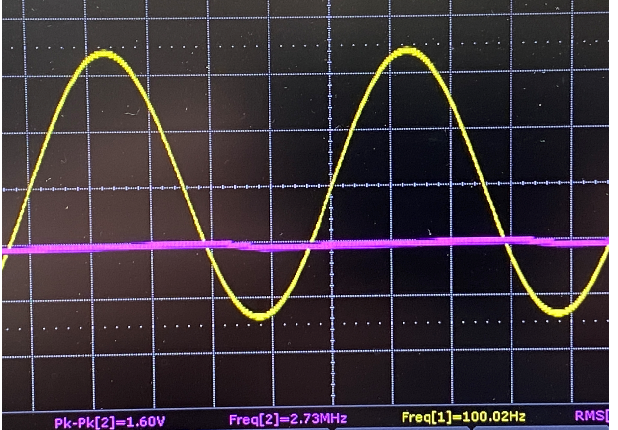
Without any signal in the meter does this:
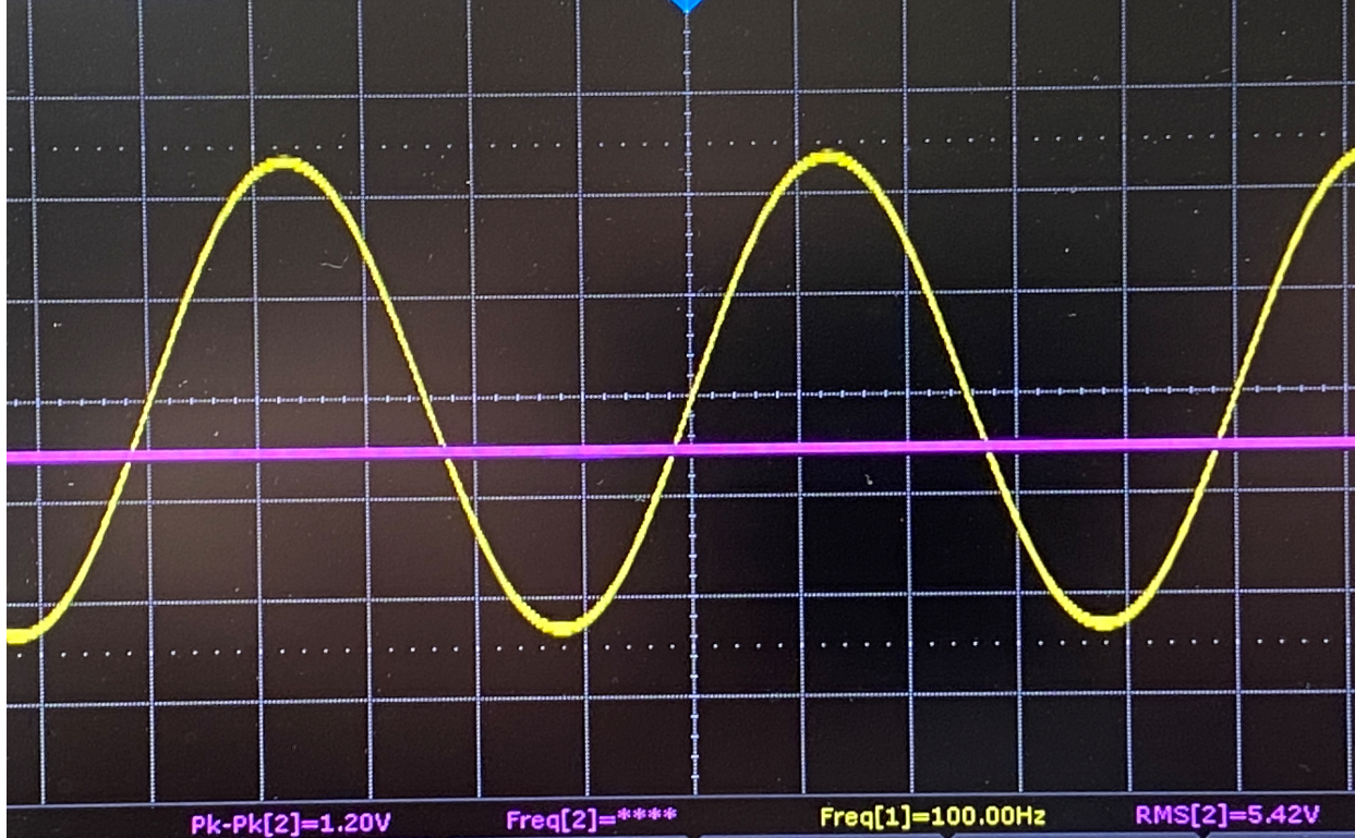
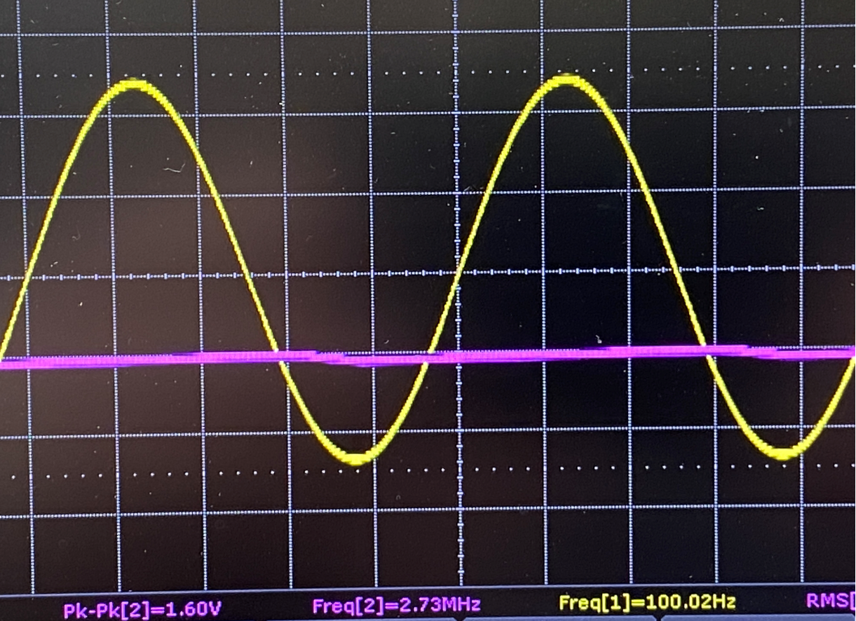
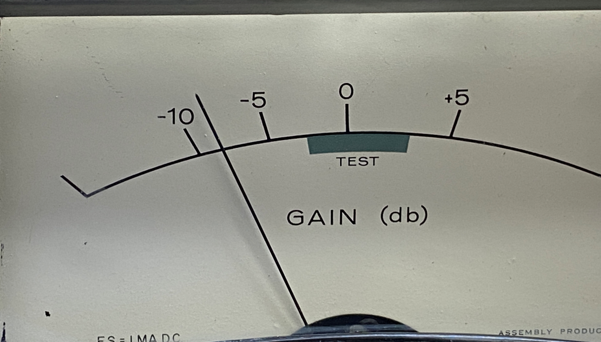
With a 1 Vrms (100Hz) differential sine wave going in and the threshold and release and attack fully counter clockwise the meter does this:
Yellow is the input sine and pink is the 1uf cap voltage:
Link555, post: 467413, member: 31690 wrote: Looking the photos
Link555, post: 467413, member: 31690 wrote:
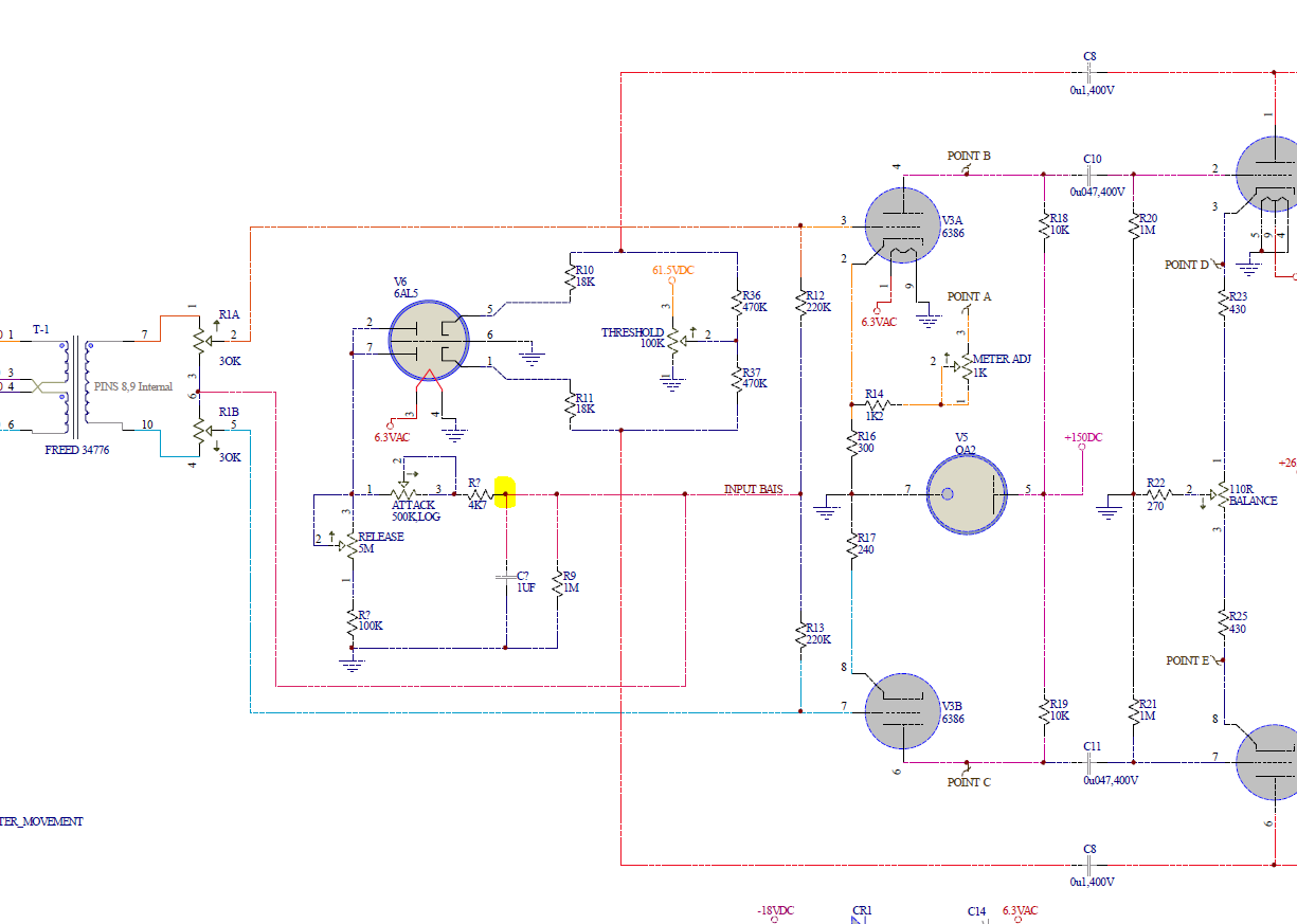
Looking the photos just now I think I have wiring error on the attack pot...I think its wired after the 1uf not before it? I will confirm tonight.
Does that come down to the same as the 1uF being on the wrong side of the attack pot (with pad resistor)? If so, then the 6AL5 anodes would be connected directly to the 1uF, which could produce very wrong results.
You show the input signal (100Hz, 1V rms), but do you know what waveform you have at the 6AL5 side of the 100nF feedback caps (both shown as C8)? It should be the full output transformer primary amplitude (one side of it) offset by the threshold pot voltage.
A control voltage of -12V d.c. (or rms!) could well be about right for that input, as the 6386 cathode voltage (and hence current through the valve) is about 20% of the quiescent. The curves for the 6386 show something of the order of a 10-fold decrease in transconductance going from a grid-cathode volts of -2 to -12.
Boswell, post: 467414, member: 29034 wrote: Does that come down
Boswell, post: 467414, member: 29034 wrote:
Does that come down to the same as the 1uF being on the wrong side of the attack pot (with pad resistor)? If so, then the 6AL5 anodes would be connected directly to the 1uF, which could produce very wrong results.
From the picture I believe the 1uF is connected directly to pins 2and 7....which I will confirm tonight and fix. Not sure what I was thinking when that happened?
You show the input signal (100Hz, 1V rms), but do you know what waveform you have at the 6AL5 side of the 100nF feedback caps (both shown as C8)? It should be the full output transformer primary amplitude (one side of it) offset by the threshold pot voltage.
Thanks should be C8 and C9...
I did take a peak there with the meter before I inject the input signal, and saw the +265Vdc on the output transformer side, and on 63VDC on the other side. THe 63VDC dropped as the threshold knob was turned clockwise.
A control voltage of -12V d.c. (or rms!) could well be about right for that input, as the 6386 cathode voltage (and hence current through the valve) is about 20% of the quiescent. The curves for the 6386 show something of the order of a 10-fold decrease in transconductance going from a grid-cathode volts of -2 to -12.
Yes I think it's getting closer, but if I have the cap wired the on wrong side of the attack pot, that could explain some of my grief.
Thanks again Boswell your input is very helpful as always!
I found my wiring error and corrected it. Now the threshold, at
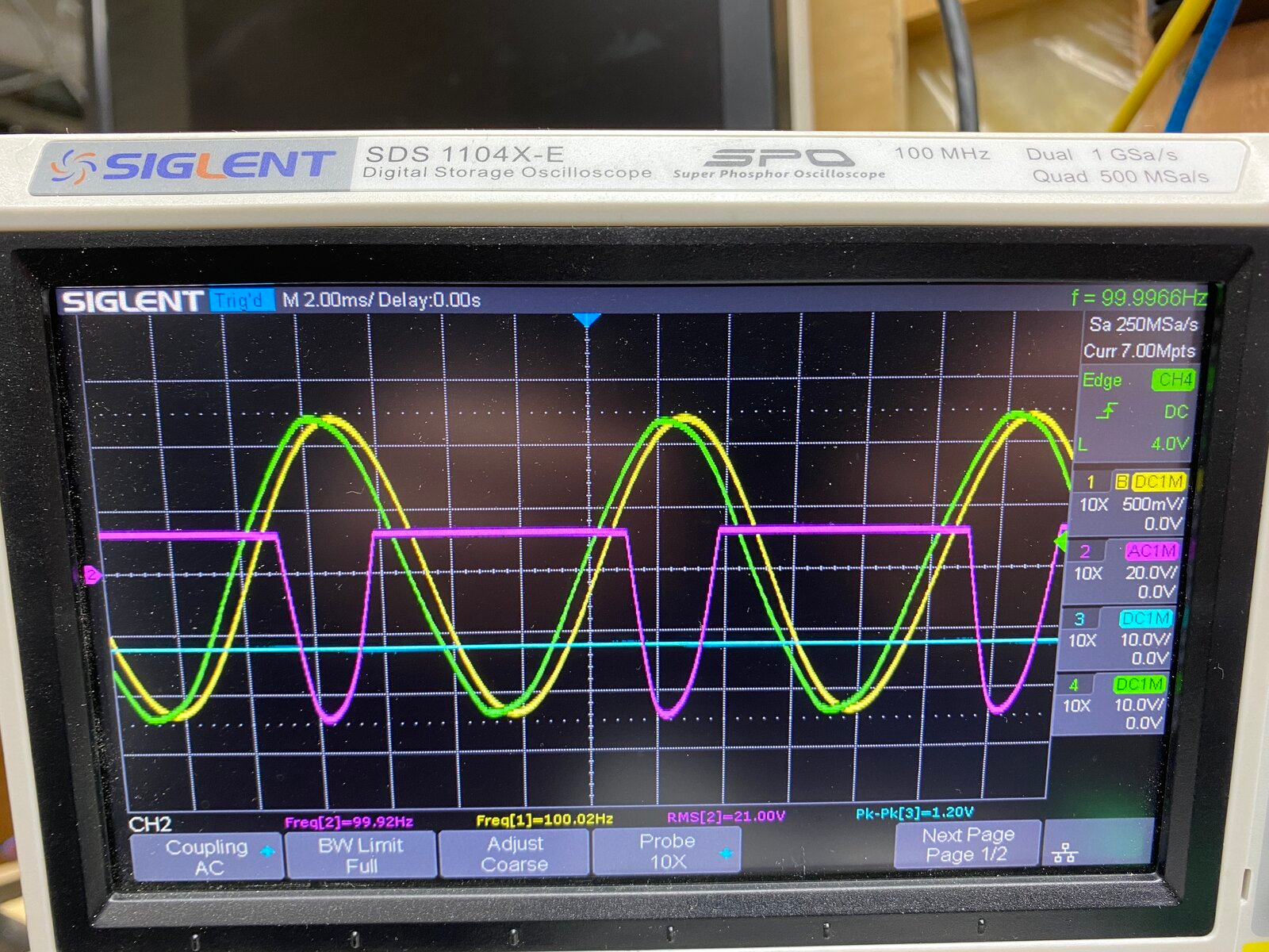
I found my wiring error and corrected it. Now the threshold, attack and release seem to be behaving better. The traces in the picture below are: Yellow- Input, one side WRT common, 500mV per division
Green- Output, one side WRT common, 10V per Division
Pink- Pins 2 and 7 of the 6AL5 WRT common, 20V per Division
Teal Blue- The top of the 1uF Cap WRT common, 10V per Division
With a 1 Vrms Sine Wave input
With a Square Wave input:
The meter is pretty much useless. I am debating reconfiguring the meter to be purely Db reduction meter.
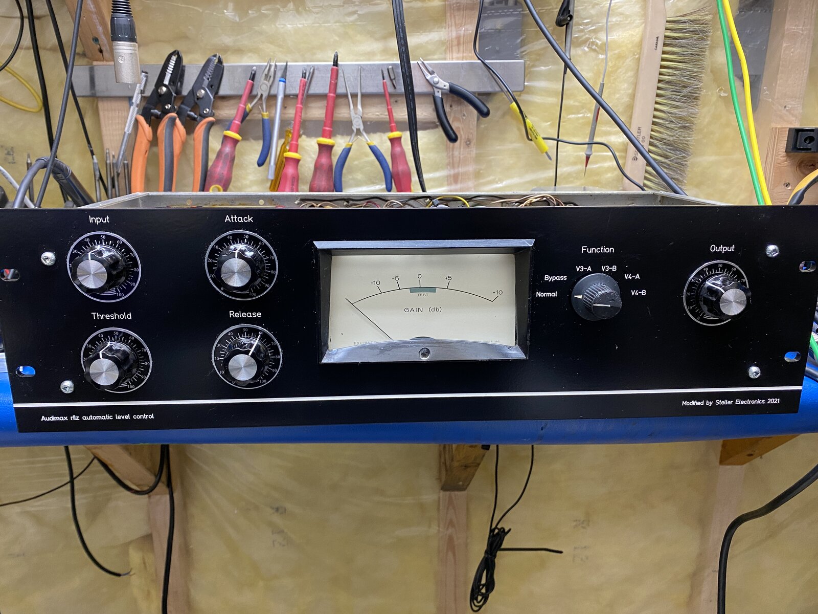
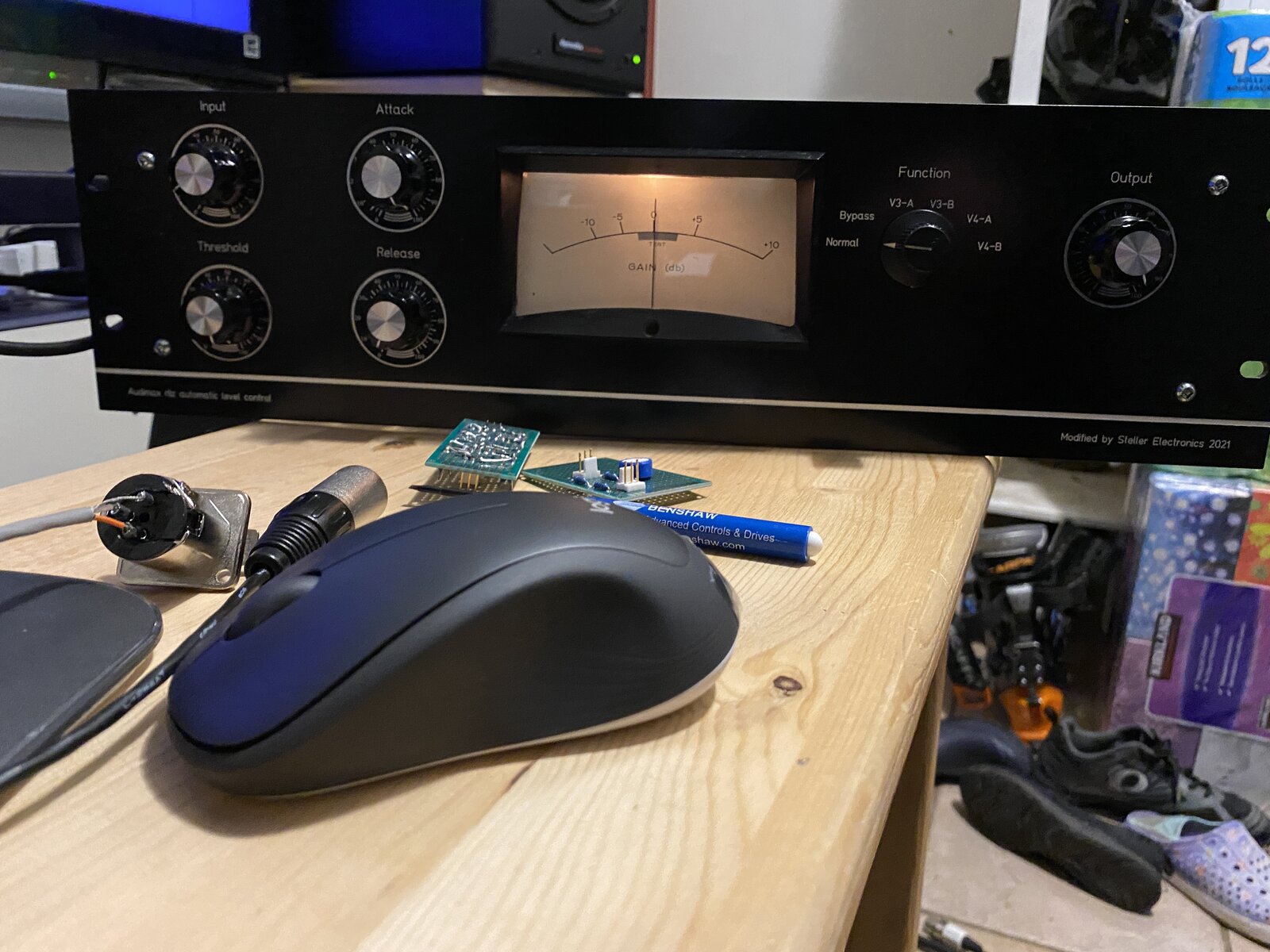
Oh and the front panel arrived!
I also experimented with a variable output pad. When I cut off the output pot that was previously added, the noise floor dropped considerably. So that needed to go. I built a balanced T pad similar to what the Gates39B had on it. It worked, but at low levels the output transformer got loaded and I could see asymmetrical distortion happening. It would be funny to put an opamp buffer on the secondary and then add a dual gain pot through another opamp output buffer.... I am thinking about a Make before break switch with 12 T Pads to attenuate....
Also The dual gang input pot has worn out sections, I will replace the 30k pot with 100k.
That's looking a whole lot better! Your new front panel is ver
That's looking a whole lot better!
Your new front panel is very smart as well. You must have a some good metalwork and screen printing firms near you who can turn round this type of job in very quick time.
When I first saw the 100Hz scope picture, I was puzzled by the apparent phase advance shown in the output vs. the input trace. Then I saw the 5V offset between them, and the distortion in the output waveform. I'm assuming you are taking the output waveform from the secondary of the output transformer, so where's the d.c. offset coming from?
Some of the apparent output offset may be due to asymmetry in the waveform. This brought up something that I had jotted down in my circuit notes, and that was that the anode of the output triode is basically a current source driving the impedance of the output transformer, so the currents flowing through the diodes on peaks would subtract from and therefore distort the output waveform - you can just see that on the green trace. This may be what gives the unit its sonic character! Have you got any way of measuring distortion?
That apart, it would be good to see a long timebase scope picture of what the control volts do when the sinewave input amplitude is changed quickly from a low value to a high value, and a second picture doing the inverse. Medium settings on attack and release.
When I first saw the 100Hz scope picture, I was puzzled by the
When I first saw the 100Hz scope picture, I was puzzled by the apparent phase advance shown in the output vs. the input trace. Then I saw the 5V offset between them, and the distortion in the output waveform. I'm assuming you are taking the output waveform from the secondary of the output transformer, so where's the d.c. offset coming from?
The output measurement is right on the the terminal strip, so on the secondary of the output transformer after H pad attenuator.. The input measurement was taken right on the output of the function generator.
Have you got any way of measuring distortion?
I can do a frequency sweep on my scope. Coupled with the function generator it has built in BODE function. That would highlight the harmonics, but I don't have proper audio analyzer like a Audio Precision.
I played with it a few times, still kind of a gimmick..... I do have a old HP spectrum analyser too. Its only good for audio frequencies.
That apart, it would be good to see a long timebase scope picture of what the control volts do when the sinewave input amplitude is changed quickly from a low value to a high value, and a second picture doing the inverse. Medium settings on attack and release.
I spent quite a bit of time playing with the controls with a pulse input, triggering on the positive and negative edge. I did not take any photos though. I will take some and post them.
Thanks Boswell!
I don't think the swept audio function is of interest for the mo
I don't think the swept audio function is of interest for the moment - that would be useful as a final test later. Your old HP audio spectrum analyser sounds like the right tool.
It would be a matter of doing separate spectrum pictures, firstly of the output of your generator, and then of the compressor output when fed with the same signal. Since the Audimax is a balanced circuit, you would expect only the level of the odd harmonics to show an increase in this sort of test. You may find that as you raise the input signal level to the point where one half of the 6386 vari-mu triode nears cut-off, some second harmonic comes in.
I'm impressed by what those Siglent scopes will do!
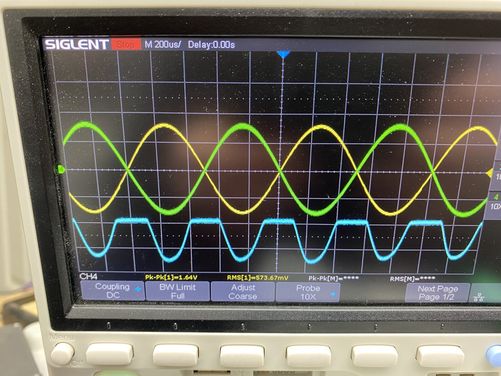
Yes sir ... broken wire.. finally noticed that today too. Yello
Yes sir ... broken wire.. finally noticed that today too.
Yellow is input +
green is input -
Blue is the output of pins 2 and 7 on the 6AL5
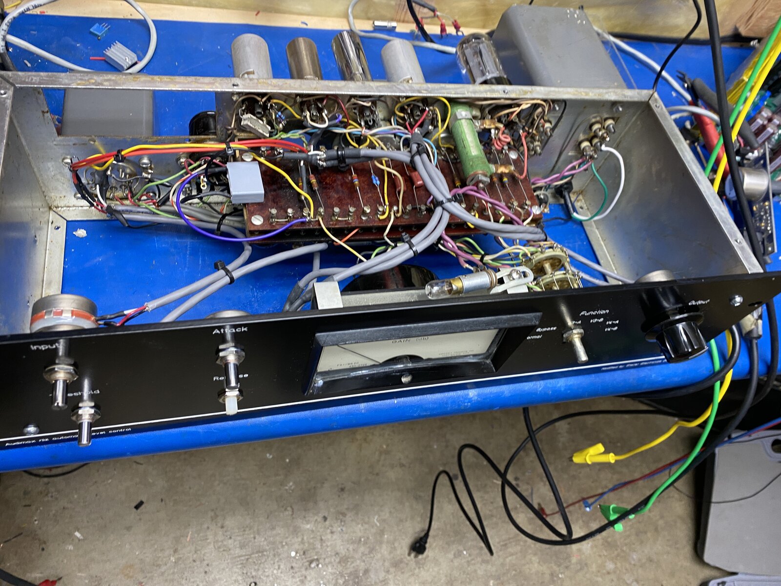
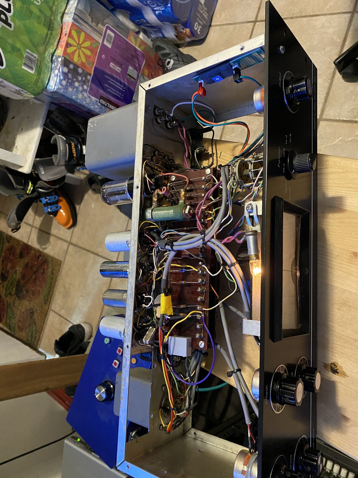
In got the face plate installed and started to clean up the wiring.
Still not happy with the meter And need to make the mounting plate for the xlrs and TRS jacks...
I tried the output control out, it does reduce the overall outpu
I tried the output control out, it does reduce the overall output down to zero, But your correct it also affects the db reduction as well. Every control on this compressor interacts, so in using the ouput control like this it almost feels natural.
The meter is thing that bothers me, the ac signal is so small compared to the dc offset. The needle doesn‘t move with with audio. I am thinking about somehow amplifing the ratio of the ac signal to the dc signal on the meter ...
It makes sense to have independent controls for input and output
It makes sense to have independent controls for input and output trims. The input trim is quite OK across the secondary of the input transformer, as that is outside the control loop. The output trim has to be on the secondary of the output transformer, as the feedback for the control voltage is taken from the ends of the primary windings.
From your scope shots, I was surprised by the amount of implied throughput gain. I have not seen an official specification for the Audimax II, but I have just found a BBC Research Department report on the Audimax II dated 1966, which is probably worth reading, that is if you can get past the BBC English and the liberal sprinkling of BBC prejudices.
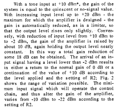
Here's an extract from the report relating to the compression characteristics (R2 is the original threshold control on the input transformer secondary):
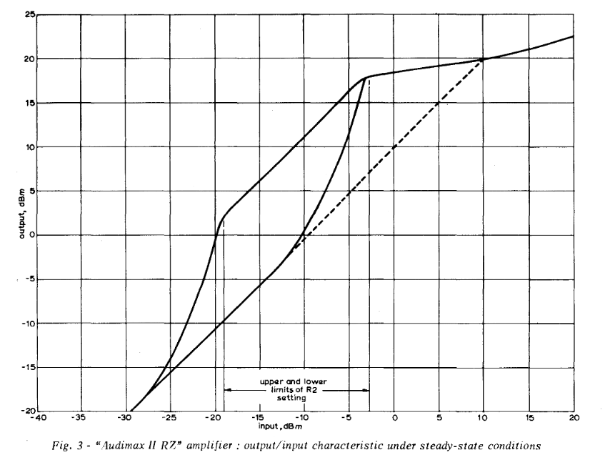
Here's a steady-state throughput graph:
The JLM mods will have changed all this, but you can get an idea of how the original design behaved, and, importantly, what the designed maximum output level was. You will have to add 6dB to this if you are running with it unloaded (dBu instead of dBm).
Link555, post: 467532, member: 31690 wrote: The meter is thing
Link555, post: 467532, member: 31690 wrote:
The meter is thing that bothers me, the ac signal is so small compared to the dc offset. The needle doesn‘t move with with audio. I am thinking about somehow amplifing the ratio of the ac signal to the dc signal on the meter ...
I don't know what you mean by the "ac signal". The meter should show the response of the Audimax to whatever signal is being applied and not the actual amplitude of the input signal. The d.c. offset is there to set the quiescent position to the 0dB mark on the meter. The deviations about that should be the amount of applied expansion or compression around that quiescent point.
That said, I don't think the JLM mod will retain the original calibration of the meter away from the 0dB mark. It should go down below 0dB (and maybe up above 0dB) as the input signal level is changed, but it's unlikely that CBS would have originally calibrated the scale to the highly non-linear control characteristic of the 6386 vari-mu triodes.
You have the option of showing the 6386 cathode volts, as on the original, or the loop control volts as generated on the 1uF cap. These will give different non-linear scales in line with the wavy transconductance of the 6386. If you choose the cathode volts, it would be best to use the mean of the volts on the two halves of the 6386, as this will be a virtual signal ground, but still represent a version of the control volts.
Maybe with the compression circuit now behaving more-or-less as the JLM mods left it, you could do a couple of steady-state calibration runs, taking readings on your DMM while you step an input 1KHz sinewave from (say) -20dBu to +20dBu. One run would be looking at the average of the two cathodes (e.g. centre point of a temporarily-added pair of 4K7 resistors), and the other would be the (negative) control volts on the 1uF cap after the dual rectifier. I think that, once you have that evidence, you will be in a position to make an informed decision about how the meter should be connected in.
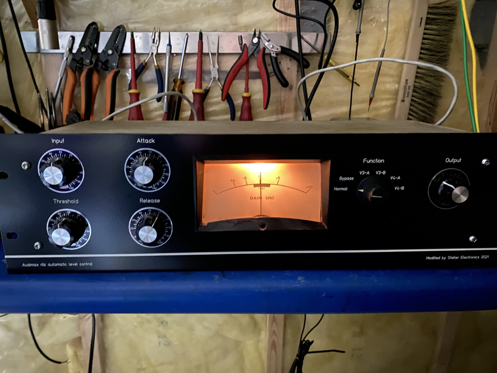
I finally hooked the unit up to my PC and sent it some audio at
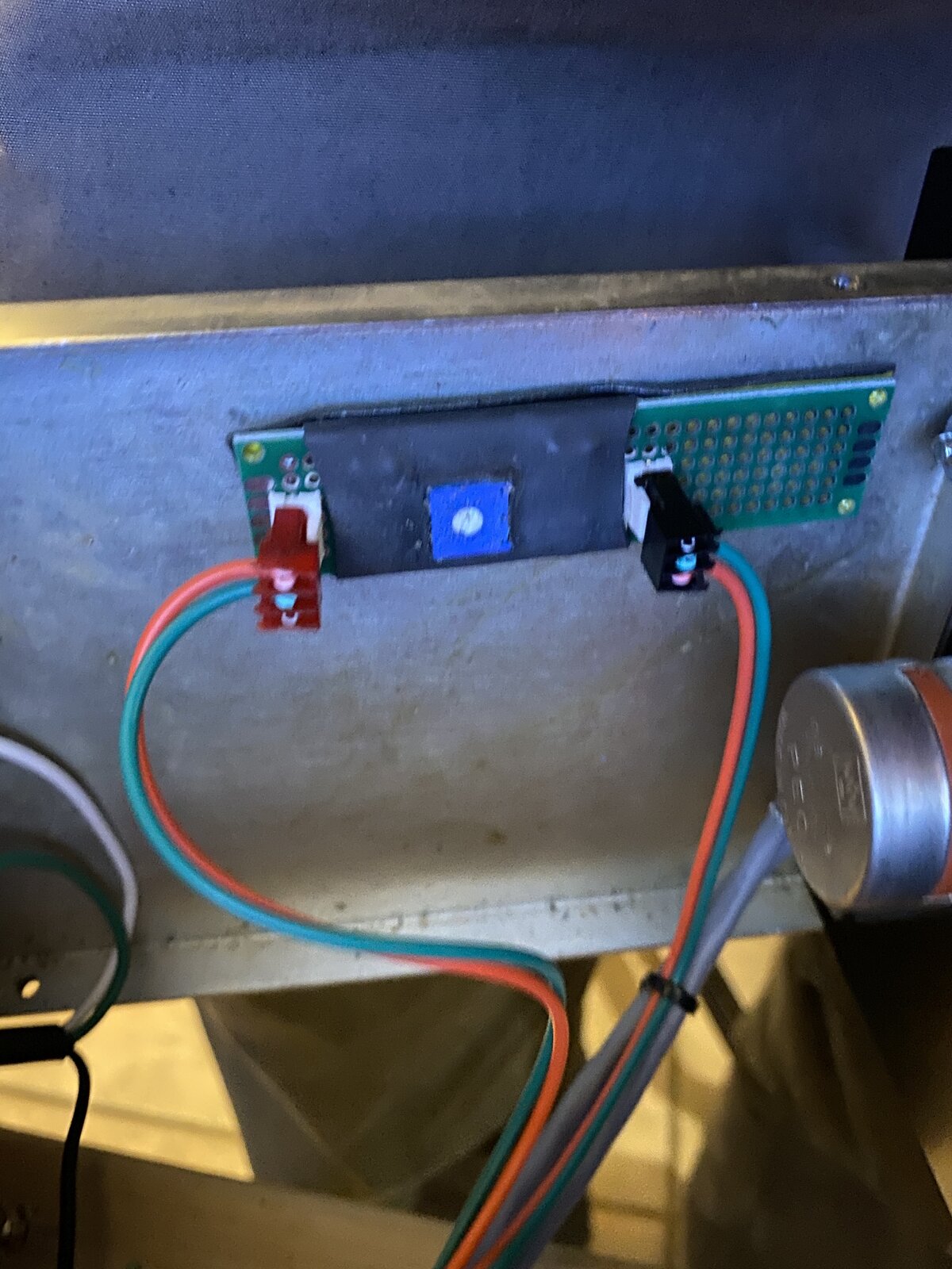
I finally hooked the unit up to my PC and sent it some audio at the proper level ...and the meter is behaving itself now. I added a h attenuator with 294 ohm resistors and 500 ohm trim pot. This will live inside the unit.
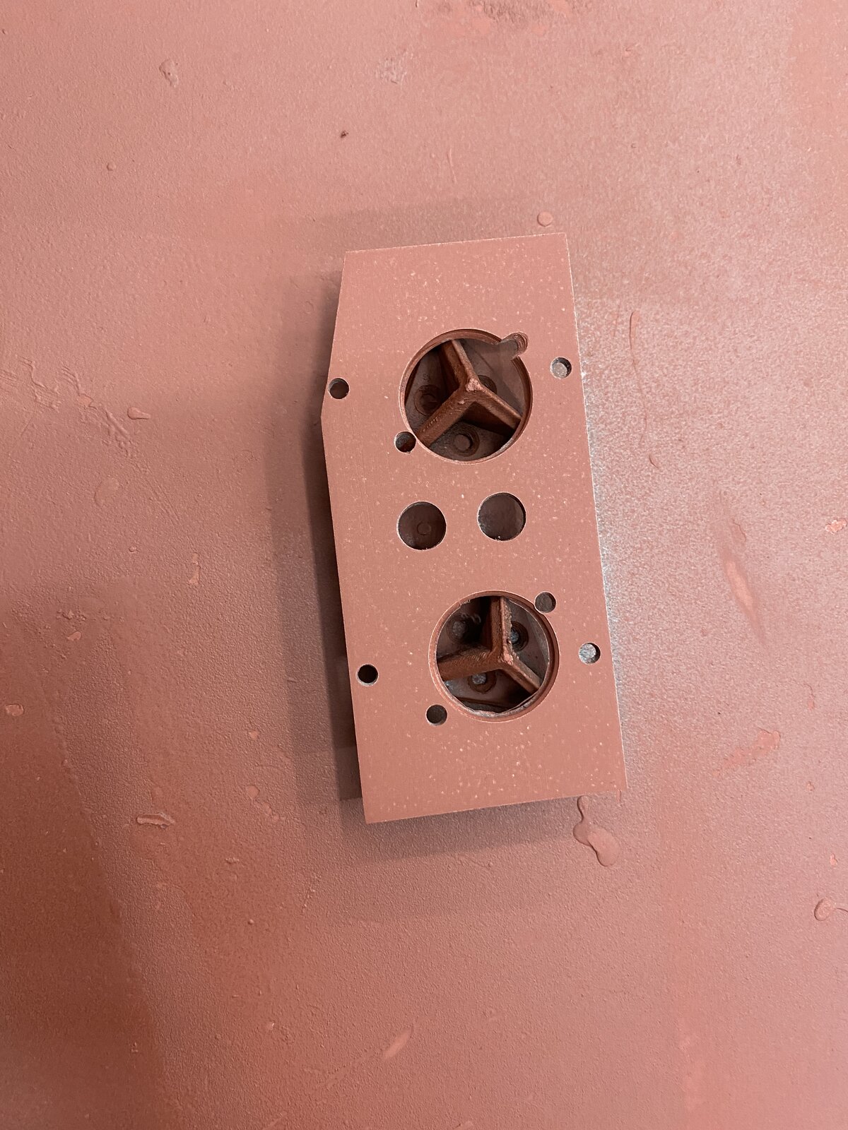
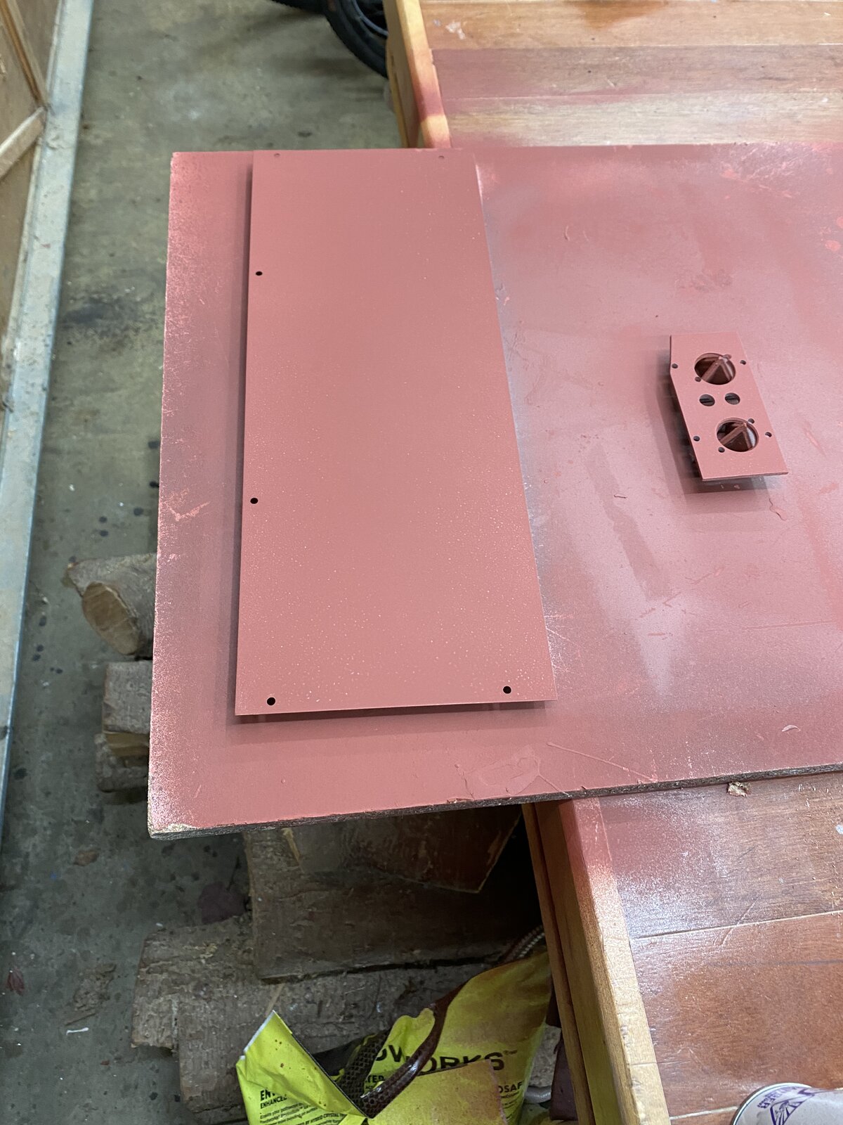
I cut the xlr and trs mounting plate and primed it.
All and all it is starting to come together. I am thinking I will leave the output knob, it allows you drive the unit to go into early saturation if you like... kind of useful.
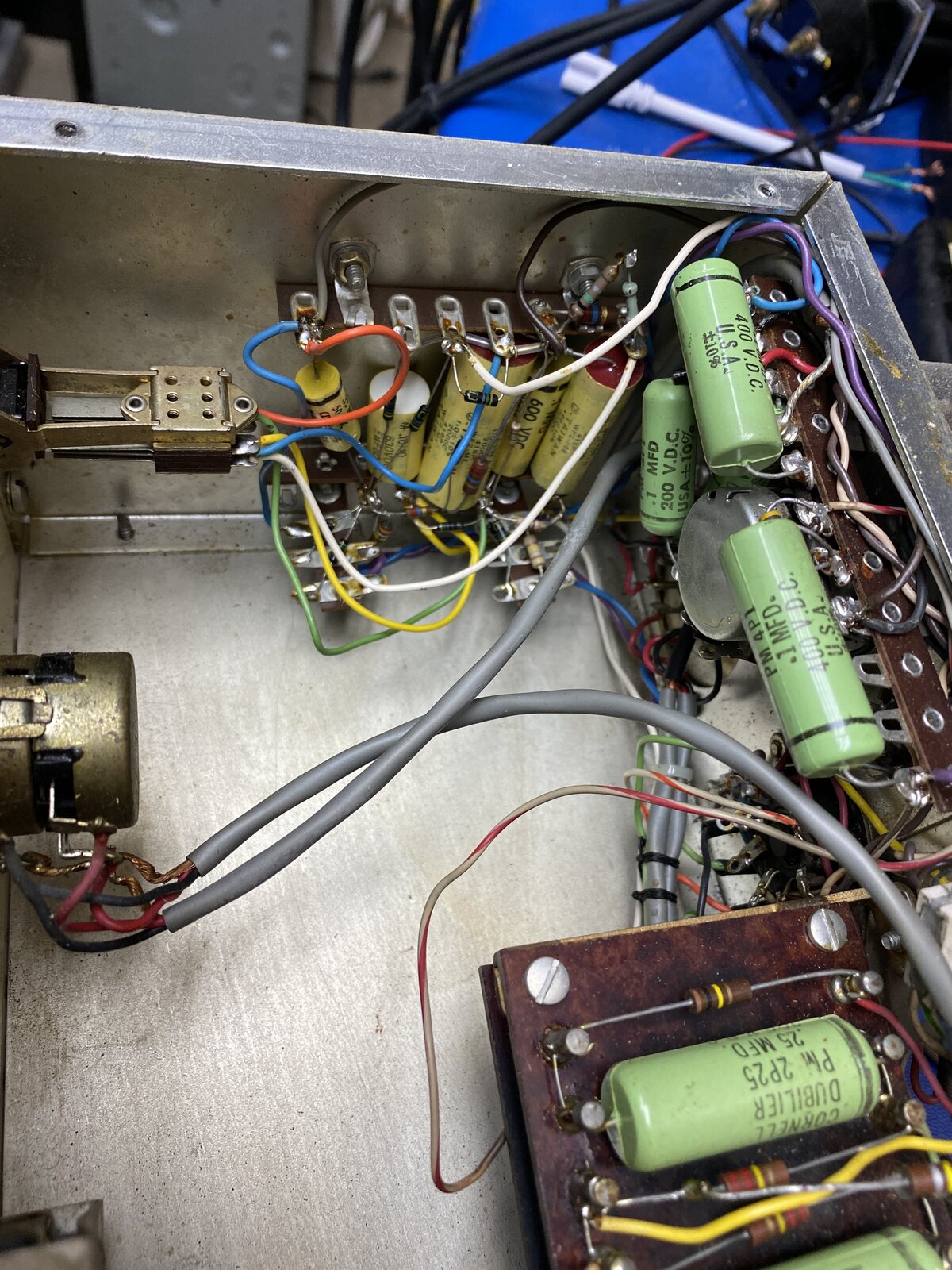
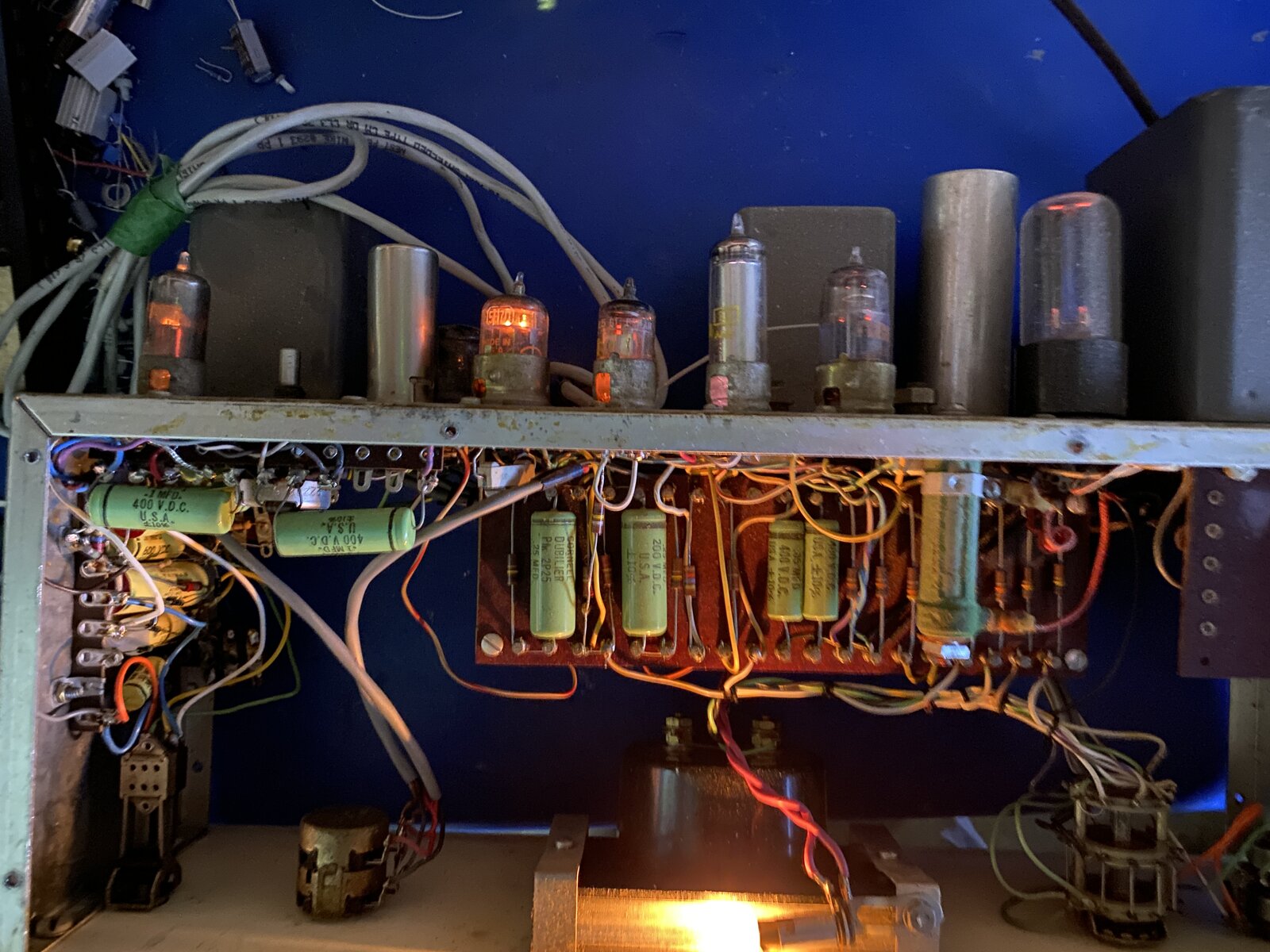
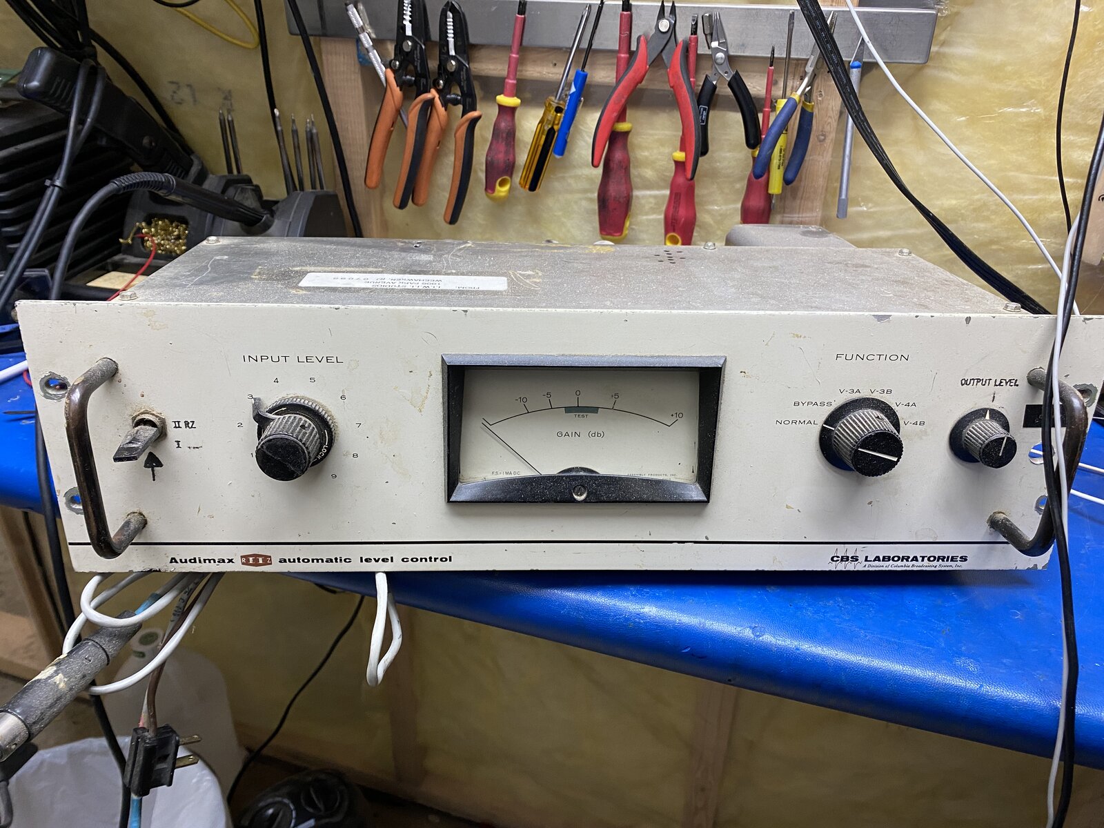
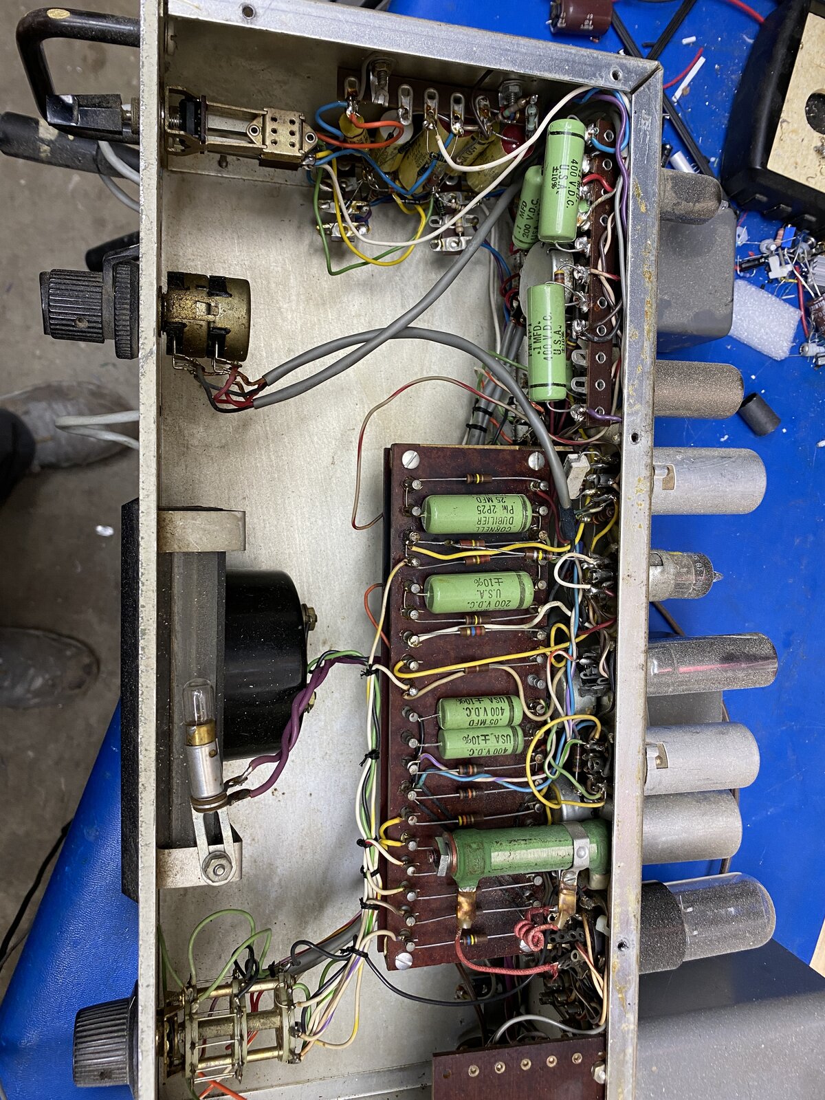



It doesn't look as though the Output Level control appears on th
It doesn't look as though the Output Level control appears on the JLM mod schematic. How was it connected? Does it actually scale the signal or does it tinker with the compression control voltage?
When reducing the level, going through a zero and then the polarity reversing is an effect you can get with vari-mu valves (or with solid-state devices) when they are used in a fully differential circuit. If there's an imbalance in the two halves of the 6386, the triode in the +ve leg may cut off before the one in the -ve leg, so the small remaining signal arrives inverted at the output. In an earlier post I mentioned that 6386s with tested matching of the two halves were difficult to obtain, and the corollary of that could be that the devices that are available are not particularly well matched for cut-off. Sometimes this can be first-order corrected by resistor scaling the grid volts on one of the triodes, but that can upset the large-signal a.c. and the standing d.c. balance as well.