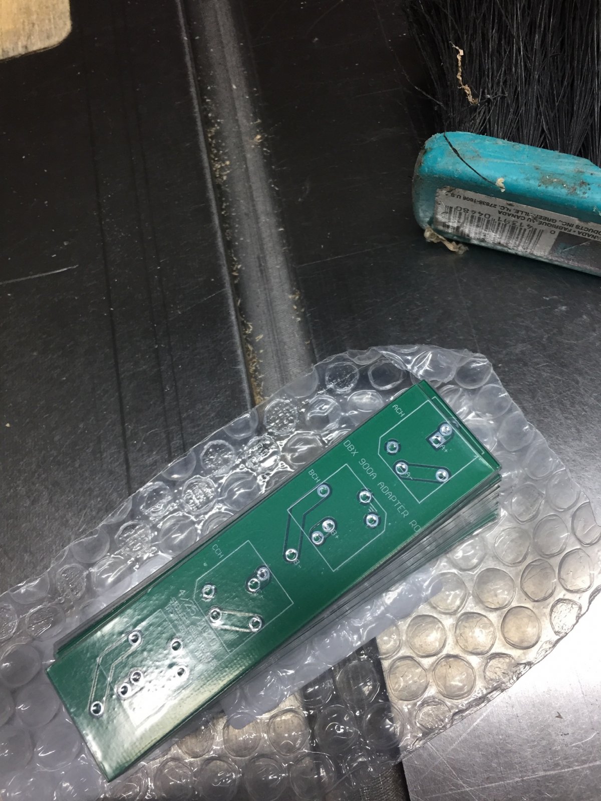
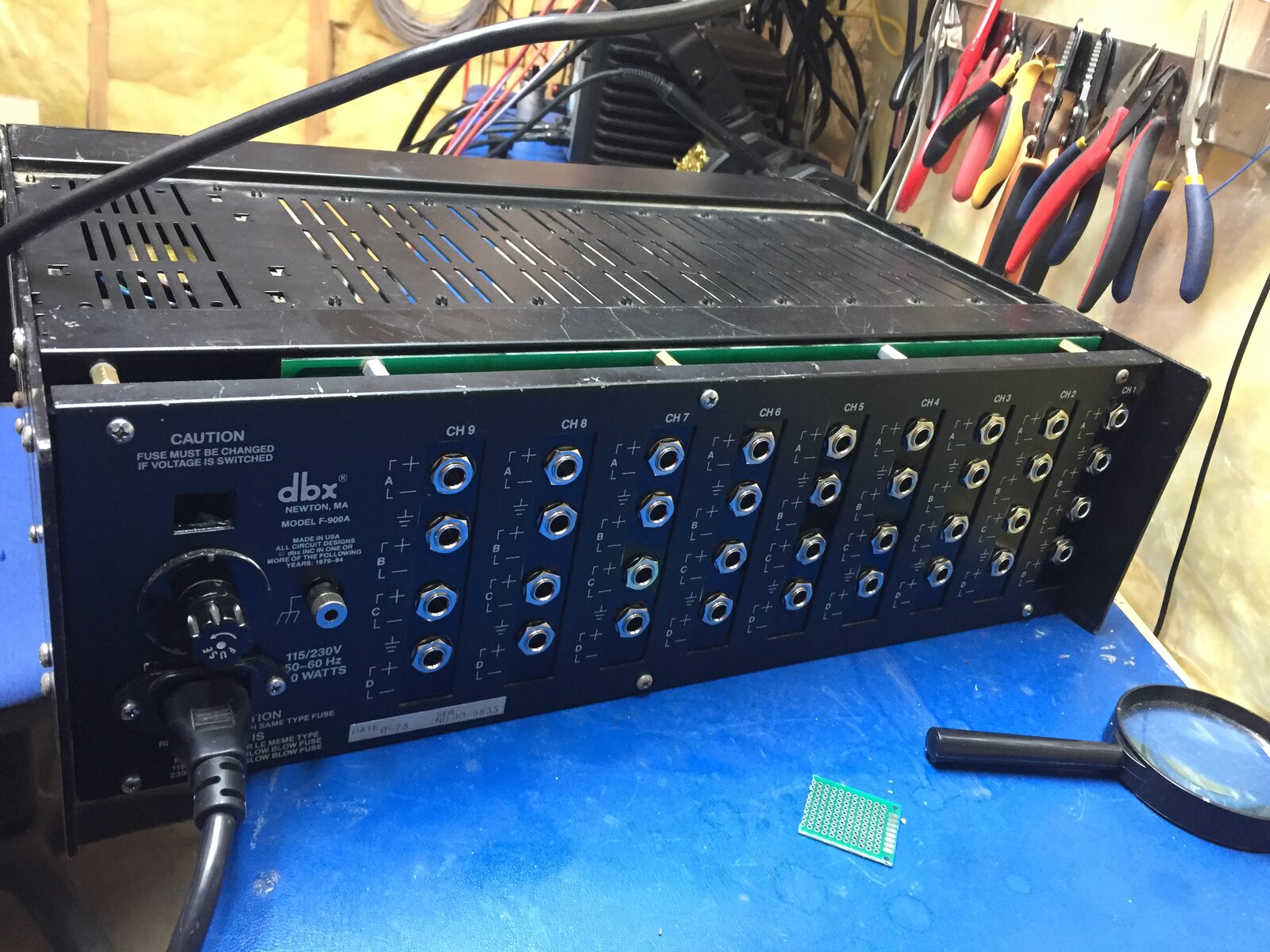
This 900a Series is in to get TRS jacks in to replace the terminal connectors. I made a Custom PCB to replace the board mount terminal connector and reuse the original metal work with a 3D printed mounting plate.
Ah-ha, the old TO-127 package! It looks like the middle 4 Darlington transistors are in this package mating with the 0.156" connectors. The outer two regulators are conventional TO-220, going directly into 0.1" sockets.
Easy to take apart, but it's a very unreliable way of connecting to power device leads. Any increase in contact resistance through ageing can quickly build into a run-away failure.
Pretty impressive! Is the rear panel in the same position as it was originally, or did you have to move it back a bit to cater for the length of the TRS sockets?
Hi everyone. I’m brand new to this forum. What a great post this is.
I picked up a “brand new” 900 series chassis and on switch on found that some idiot had replaced the toroidal and swapped wires on the voltage selector switch, so fried the toroidal and the PSU board. Whilst I’m sure it’s salvageable, I got to wondering if I should build an external PSU using new switch modes or linear PSUs. My concern is that such modern supplies may introduce noise into the analog circuitry of the modules, but of course I don’t have enough experience for this to be any more than a thought. Im wondering if anyone has experience with such an approach?
Hi GavinO welcome to the forum. Personally I would stay with the Linear power supply as it is easier to get a lower noise solution. But it will be likely a be more expensive than an offline switcher because of the toroidal transformer. If you need help with it let me know. All the best.
Hi GavinO welcome to the forum. Personally I would stay with the Linear power supply as it is easier to get a lower noise solution. But it will be likely a be more expensive than an offline switcher because of the toroidal transformer. If you need help with it let me know. All the best.
@Link555
thank you so much for your reply. I managed to find some suitable Linear supplies from Bel Power, but to get the two down here in South Africa is about $350 so I could just as well pick up a used chassis online for the same money.
So I’m kinda torn as to which route to take. Maybe I should get another chassis for short term use and take my time fixing the damaged PSU? Whilst this sounds like the obvious route to follow, I’ve read comments on another forum about the added value of having some power headroom available in the case of a fully loaded chassis.
Gavin
Sorry I was under the impression you wanted to repair the stock power supply rather than replace it, depending on the Damage that might be a cheaper option.
Comments
Circuit boards came today... a couple stand offs and 3D printed
Circuit boards came today... a couple stand offs and 3D printed insert and this will work!
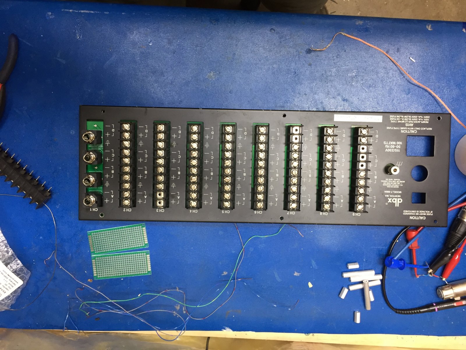
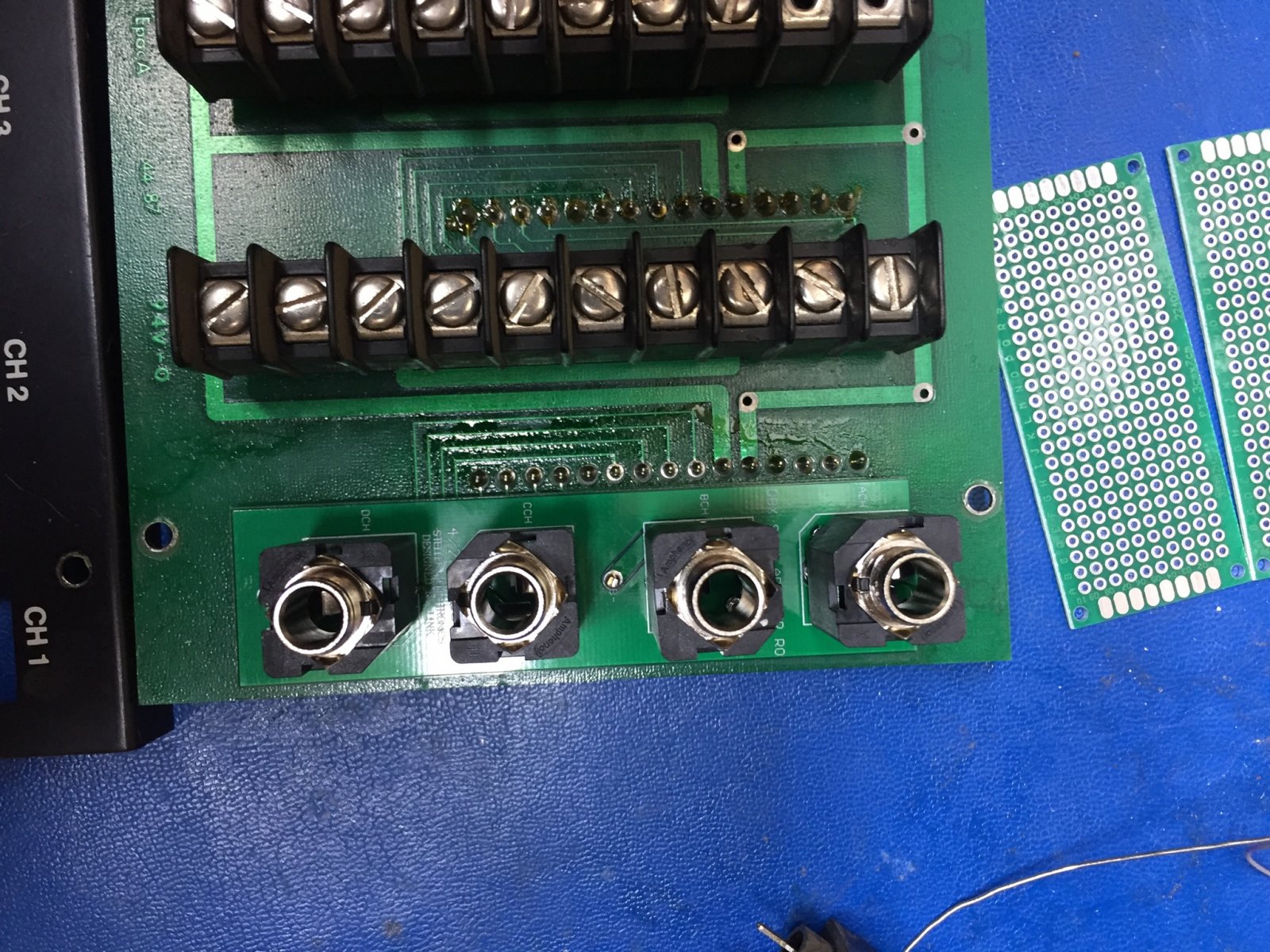
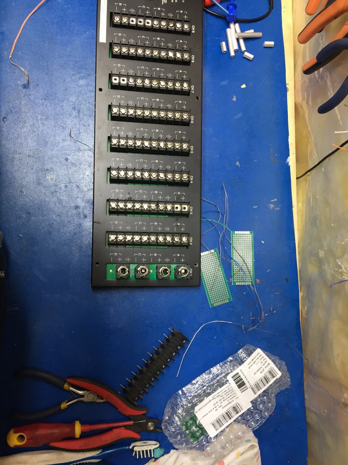
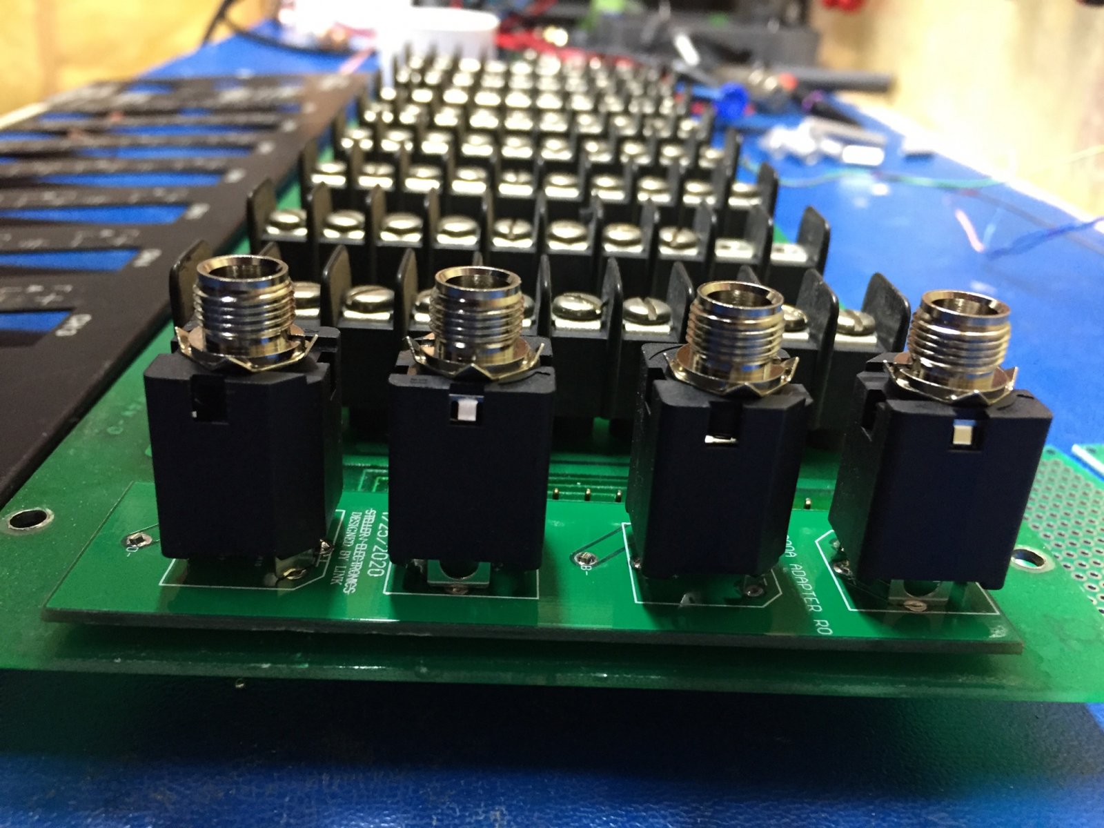
Desoldering was a lot of work.....but it's finally done..
Nice work!
Nice work!
Now onto the Power supply. Just doing some recapping. Interest
Now onto the Power supply. Just doing some recapping. Interesting design the Power transistors are connector mounted...
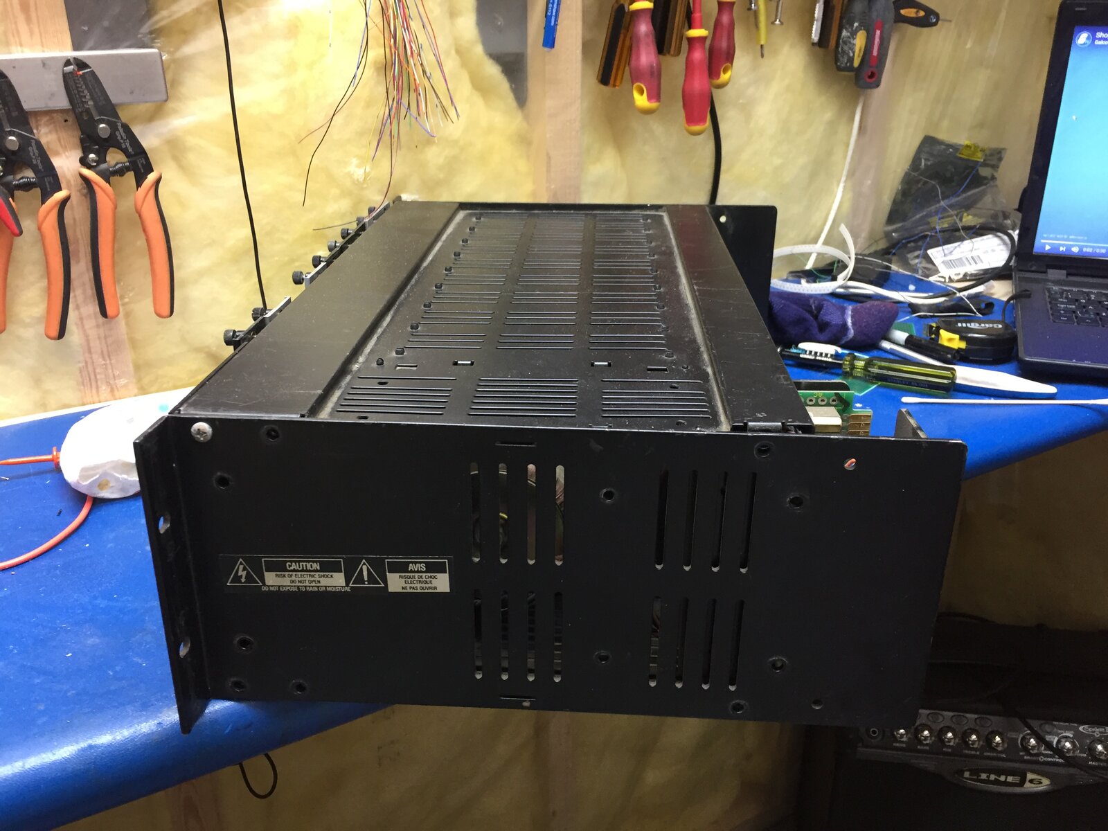
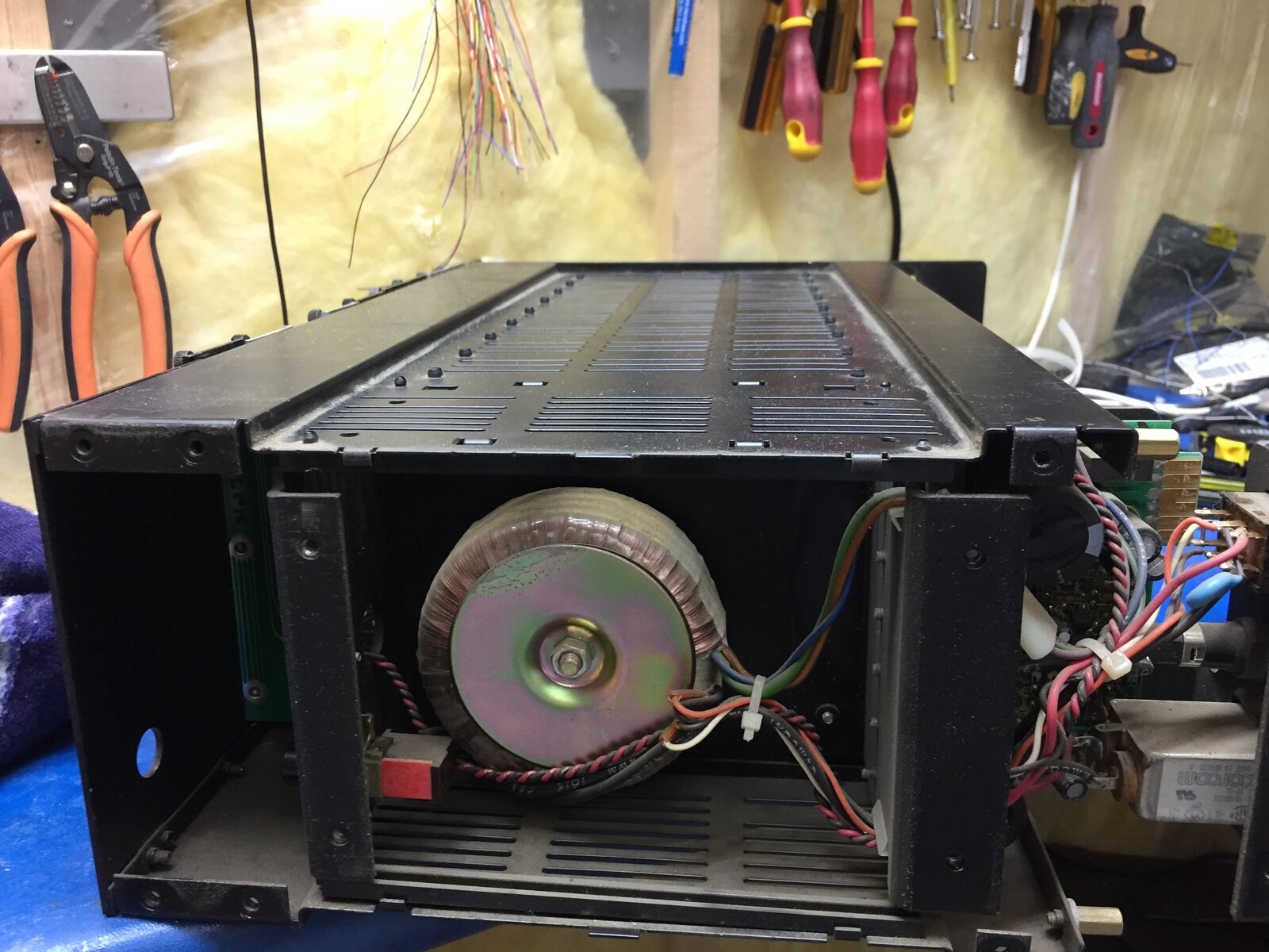
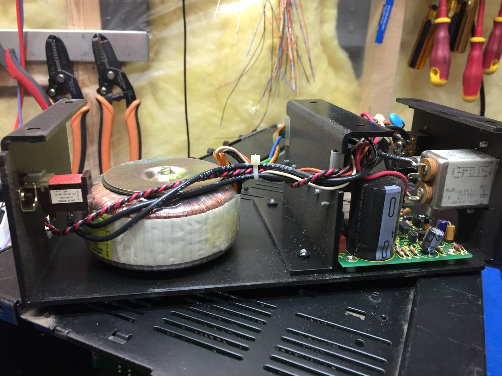
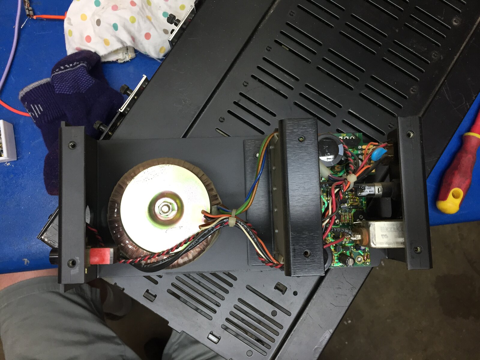

One more of the PCBA
One more of the PCBA
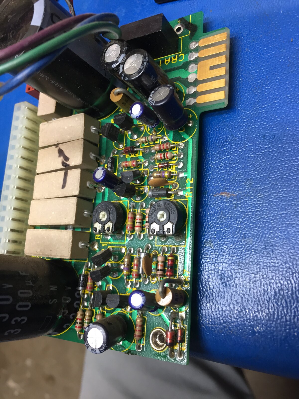
Ah-ha, the old TO-127 package! It looks like the middle 4 Darlin
Ah-ha, the old TO-127 package! It looks like the middle 4 Darlington transistors are in this package mating with the 0.156" connectors. The outer two regulators are conventional TO-220, going directly into 0.1" sockets.
Easy to take apart, but it's a very unreliable way of connecting to power device leads. Any increase in contact resistance through ageing can quickly build into a run-away failure.
Exactly what I was thinking, I might be taking that connector of
Exactly what I was thinking, I might be taking that connector off and soldering straight to the pcb
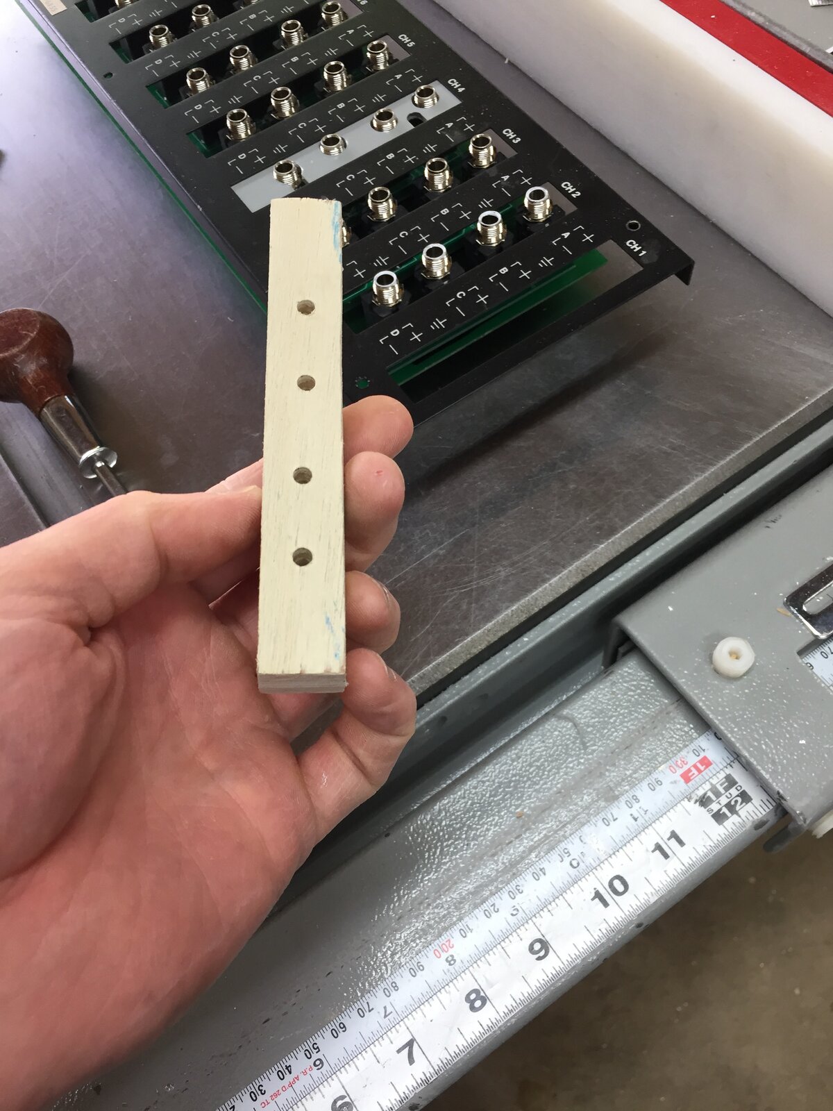
Well the plate is done.... 38 holes and two squares later... not
Well the plate is done.... 38 holes and two squares later... not bad for a sparky..


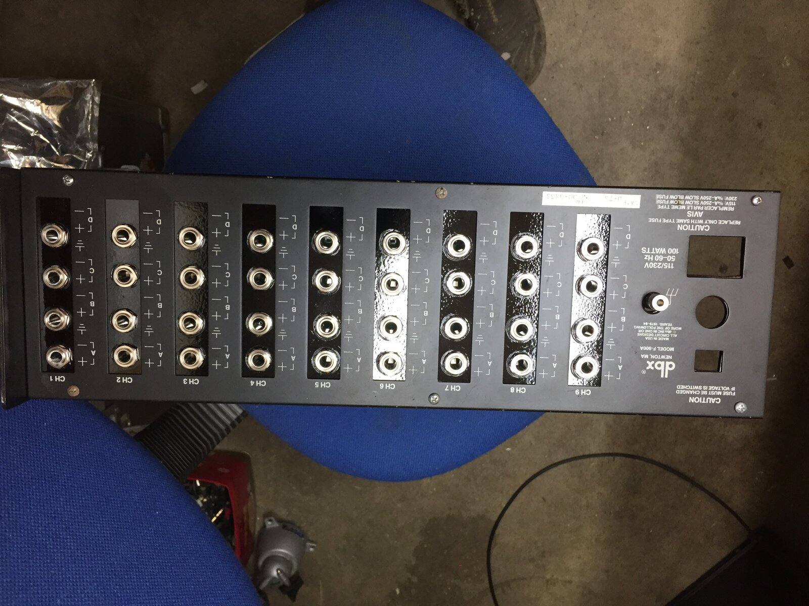
Pretty impressive! Is the rear panel in the same position as it
Pretty impressive! Is the rear panel in the same position as it was originally, or did you have to move it back a bit to cater for the length of the TRS sockets?
Actually I brought the back out further, the racks has wings the
Actually I brought the back out further, the racks has wings the project backwards ...so it works
Power Supply Recapped and Transistors and IC soldered directly t
Power Supply Recapped and Transistors and IC soldered directly to the PCB. I removed the connector to hopefully increase the future reliability...
![IMG_8355[1].JPG](/sites/default/files/attachments/464336=19585-IMG_8355[1].JPG)
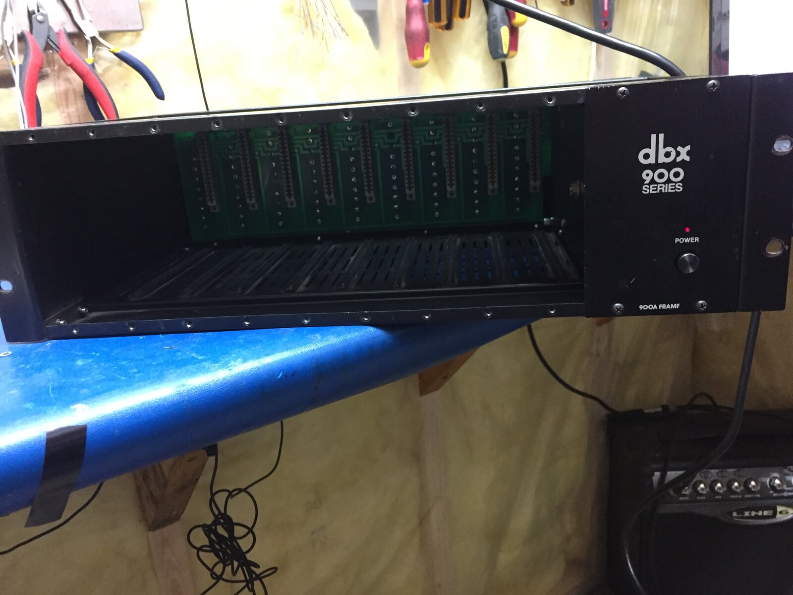
With a little fiddling I got the DBX 900 chassis back together a
With a little fiddling I got the DBX 900 chassis back together and working.... Now onto the card repairs...

And now repairing 8 dbx 900 series cards... 6 904 noise gates an
And now repairing 8 dbx 900 series cards... 6 904 noise gates and 2 903 compressors.
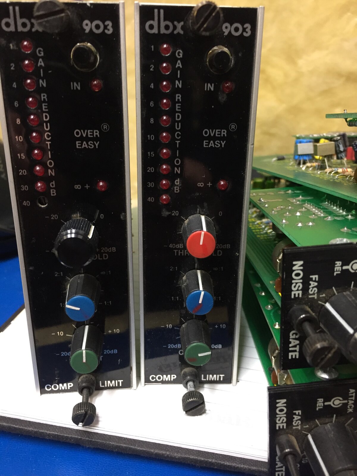
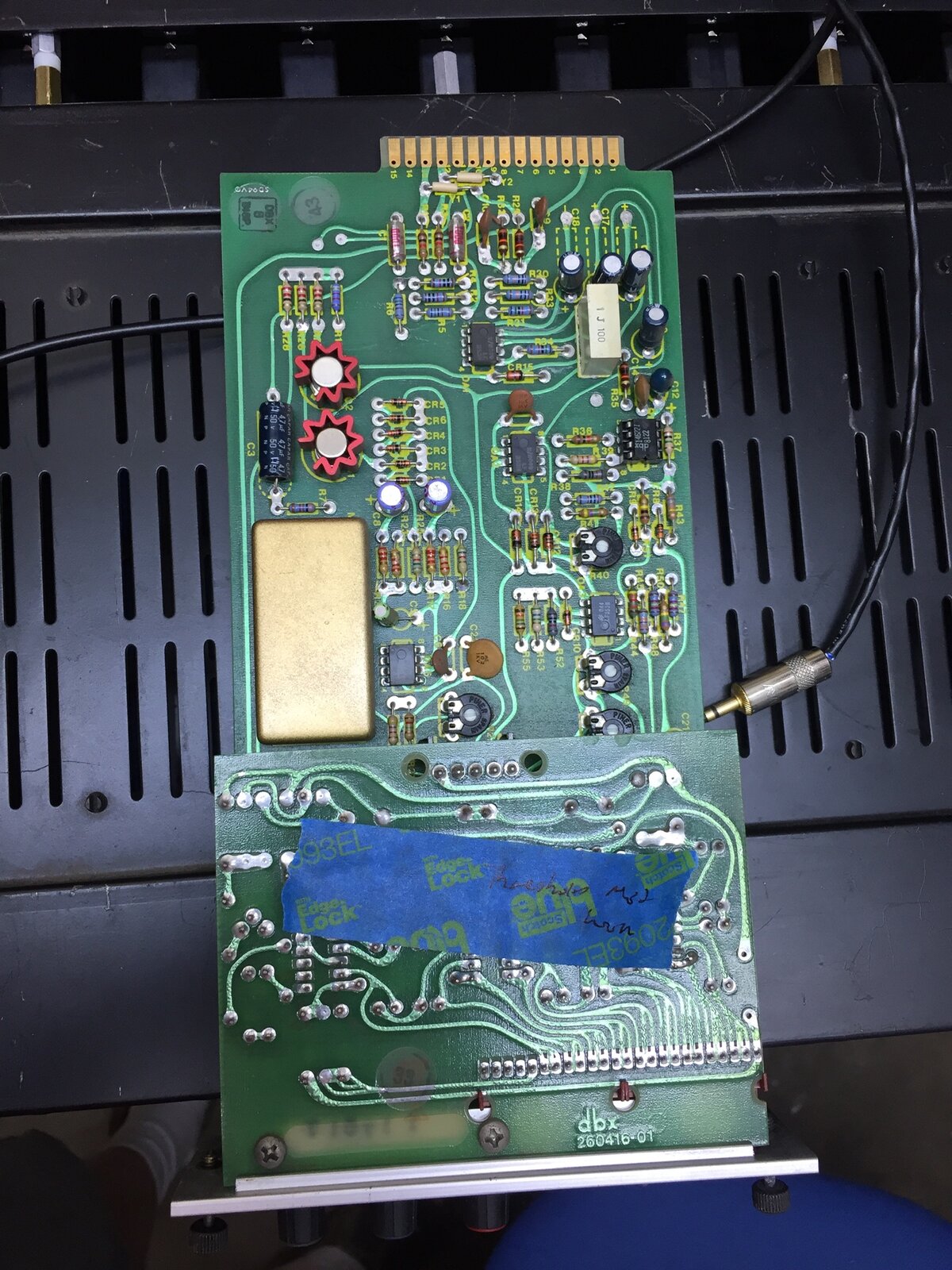

One compressor was the worst off three funky opamps and one internally disconnected 20k threshold pot.
Repairs done cards inserted and blank off panel made...tested an
Repairs done cards inserted and blank off panel made...tested and ready for pick up...
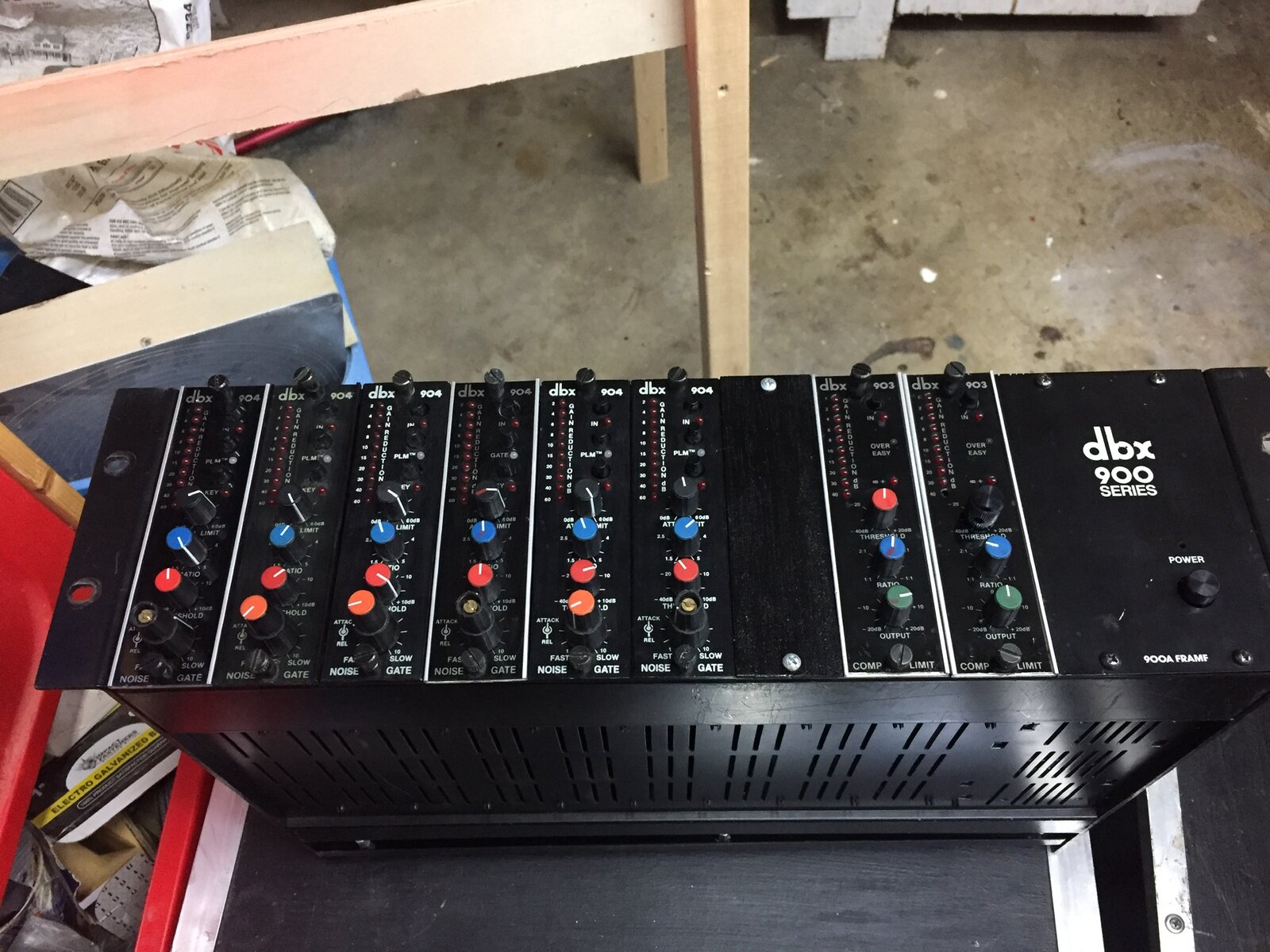
Looks like.a job well done!
Looks like.a job well done!
Awesome post on dbx 900 Mods
Excellent post you did here, Link!
In reply to Awesome post on dbx 900 Mods by audiokid
Thanks Chris
Thanks Chris
F900 PSU Substitution
Hi everyone. I’m brand new to this forum. What a great post this is.
I picked up a “brand new” 900 series chassis and on switch on found that some idiot had replaced the toroidal and swapped wires on the voltage selector switch, so fried the toroidal and the PSU board. Whilst I’m sure it’s salvageable, I got to wondering if I should build an external PSU using new switch modes or linear PSUs. My concern is that such modern supplies may introduce noise into the analog circuitry of the modules, but of course I don’t have enough experience for this to be any more than a thought. Im wondering if anyone has experience with such an approach?
GavinO wrote: Hi everyone. I…
Hi GavinO welcome to the forum. Personally I would stay with the Linear power supply as it is easier to get a lower noise solution. But it will be likely a be more expensive than an offline switcher because of the toroidal transformer. If you need help with it let me know. All the best.
Link555 wrote:Hi GavinO…
@Link555
thank you so much for your reply. I managed to find some suitable Linear supplies from Bel Power, but to get the two down here in South Africa is about $350 so I could just as well pick up a used chassis online for the same money.
So I’m kinda torn as to which route to take. Maybe I should get another chassis for short term use and take my time fixing the damaged PSU? Whilst this sounds like the obvious route to follow, I’ve read comments on another forum about the added value of having some power headroom available in the case of a fully loaded chassis.
Gavin
@Link555 thank you so much…
Sorry I was under the impression you wanted to repair the stock power supply rather than replace it, depending on the Damage that might be a cheaper option.