Hi gang,
You know I own a few Focusrite ISA preamps. I'm considering buying a few attenuators to allow me to drive the transformer a bit harder and try to pull out a bit more mojo.
I currently record tracks with a peak range between -18db to -10db (on the preamp and on the DAW).
So my question is ; is it worth it ? Do pushing the transformer a bit more allow a more colored sound ?
About this item :
https://www.amazon.ca/dp/B0060GDZTG/?tag=r06fa-20
Comments
kmetal, post: 461171, member: 37533 wrote: I would be curious to
kmetal, post: 461171, member: 37533 wrote: I would be curious to hear the attenuator in series, just to hear how the isa saturates.
Sufficient attenuation between the output of a pre-amp and a following ADC allows the ADC to capture either the effect of transformer saturation or the onset of clipping, whichever is appropriate for the pre-amp's output architecture.
I've done a bit more digging in the Focusrite literature, and, from what I can tell, the ISA One, Two, 428 and 828 are based on a common design that has input transformers only and no output transformers. The information is well hidden, but with these models, it looks as though the output will clip.
Boswell, post: 460601, member: 29034 wrote: Here you are: Hey @B
Boswell, post: 460601, member: 29034 wrote: Here you are:
Hey Boswell, would you be kind enough to calculate what the values for a 40db would be?
It's a question Faraz Abtahi&lc=UgzYWiXPVhZb9HSBUcp4AaABAg'">il asked on my youtube channel.
This is for the U-pad in your balanced attenuator, right? Well,
This is for the U-pad in your balanced attenuator, right? Well, 40dB is easy, as it's 100x in voltage and hence ratios. To 1%, you can use a shunt of 2R and series of 100R. Series resistors of 10K Ohms and a shunt of 200 Ohms are readily available values, and would work OK in this configuration (where OK is not a short circuit). Use two 100 Ohms in series if you can't get 200 Ohms, but if you are considering that, then 4.7K series and 2x 47 Ohm shunt would work marginally better over the range of other likely circuit impedances.
Boswell, post: 462289, member: 29034 wrote: This is for the U-pa
Boswell, post: 462289, member: 29034 wrote: This is for the U-pad in your balanced attenuator, right? Well, 40dB is easy, as it's 100x in voltage and hence ratios. To 1%, you can use a shunt of 2R and series of 100R. Series resistors of 10K Ohms and a shunt of 200 Ohms are readily available values, and would work OK in this configuration (where OK is not a short circuit). Use two 100 Ohms in series if you can't get 200 Ohms, but if you are considering that, then 4.7K series and 2x 47 Ohm shunt would work marginally better over the range of other likely circuit impedances.
Thanks a lot, I'll relay that answer..
Hello 5 years later, I'm a…
Hello 5 years later,
I'm a new member and would like to bring this topic back for an attenuator I'm going to build. The objective is exactly the same but I would like to have 3 settings (2 different attenuation options plus a bypass) so as Boswell said I would need a 3 steps toggle switch (on - off - on). I've spent the past week researching and trying to understand switches better, but I'm still fairly confused on which type of switch would be needed for this. DPDT doesn't seem to allow for enough options to get 3 different settings, but (if my understanding is correct) a 3PDT also wouldn't do the job as I would probably need 3 throws? Am I correct or completely off the rails?
Thank you
Hi Giulio, You can either do…
Hi Giulio,
You can either do this simplistically or precisely. Which you do depends on the output impedances of the devices that are likely to drive the attenuator and the input impedances of the devices that the attenuator has to drive.
If you can say that the driving impedances are 100 Ohm or less and that the driven impedances are 10K Ohm or more, then the simple method is all you need to get attenuation accuracies of about 1dB. However, if you are working, for example, in a 600 Ohm environment, then you need a much more precise configuration.
You also don't say whether you want more than one signal channel, and if so, do you need the attenuations to switch in channel pairs (e.g. as in a stereo attenuator).
The simple fixed balanced attenuator is a U-pad. This has two equal resistors (R1) connected to the + and - inputs, and a single different resistor (R2) connected across the free ends of the R1 resistors. The + and - output signals are taken from across R2. If you sketch this, it's easy to see that if the input is balanced, the mid-point of R2 will be at zero volts. This is why R2 values are often given as 2xR2. If you put a vanity mirror on edge along the centre line, you will see the symmetry.
To turn this into a switchable atenuator, simply use a SPDT switch to select one of two different resistors for R2. If the switch has a centre-off position, then selecting that gives an approximately zero attenuation setting. Make sure you always take the output from the ends of the two R1s, irrespective of the switch setting. Note that a stereo (2-channel) version can be made using a single DPDT switch.
Attenuation ratios are easy to calculate. If R2 represents half the physical value of the actual shunt resistor, then the attenuation is approximately R2/(R1+R2). The tricky bit is to choose resistor values that allow your different attenuations without too much variability due to the change in attenuator output resistance driving the unchanged load.
As a simple example, a 6dB -12dB attenuation (2x or 4x voltage drop) could be done with a pair of 1.5K Ohm input resistors (R1) and switch selection of 3K or 1K shunt resistors (R2). Each leg of the circuit then would have either 1.5K/(1.5K + 1.5K) = 1/2 or 0.5K/(0.5K + 1.5K) = 1/4.
Good luck!
Thank you so much Boswell! …
Thank you so much Boswell!
Sorry if I didn't describe in enough detail. The project aim is almost exactly the same as pcrecord: I would like the option to drive my 4 SoundSkulptor MP573 preamps (600 Ohms output impedance) without clipping in my ADC (RME Fireface UC extra line inputs in the back - 10k Ohm input impedance). The output gain pot on the MP573 allows for approximately -10dB attenuation, but as suggested by the manufacturer, in certain circumstances I would like to try driving the output transformer as well, and filling 500 series slots with the SoundSkulptor PADs is not an option for me, which brought me to reading this forum.
So just like pcrecord my aim is to build a 4 mono channels passive attenuator, all balanced, with 3 settings (I'm thinking -0dB, -12dB, -24dB). Besides perhaps having different attenuation values, the only addition would be a bypass setting so that I don't have to go behind the desk to unplug/replug the preamps output every time I don't need attenuation post-transformer. It's not an indispensable option but I also like to challenge myself and therefore here I am trying to take this extra step, especially once I'm willing to put the effort into building it myself.
Reading your response I clearly still have some homework to do:
1. my first mistake was thinking I'd have to create different U pads for each attenuation setting, whereas now my understanding is that switching between different shunt resistors (R2) would be enough to change the level of attenuation (which makes a lot of sense).
2. I'm still trying to wrap my head around the wiring when it comes to the switch. I will do new sketches of the schematics and wiring, taking into consideration what you just commented (I'm also collecting all the previous suggestions, pictures and drawings on this thread as they seem to help a lot!). Follow up questions will likely arise!
Thank you so much for taking the time to respond. If the details I've added bring up other/new considerations it would be amazing and surely useful to read them.
Gratefully, Giulio
When set for +4dBu nominal…
When set for +4dBu nominal level inputs, the FireFace UC has a 15dB overhead on that, so the peak clipping level is +19dBu. The MP573 is specified as having a peak output level of +27dBu, but the spec does not say whether that is when driving 600 Ohms or a high impedance. However, the schematics show an 820 Ohm resistor across the output, and that may be there to give a 600 Ohm figure.
You are caught having to deal withf a possible 600 Ohm source and a high-impedance load, but it means you should not need more than 8 - 12dB of attenuation between the MP573 and the FireFace UC line input. It seems very remiss of Sound Skulptor not to give figures for output impedance, as they should anticipate this pre-amp being incorporated in a pro-level gear chain.
It terms of calculating attenuation resistor values, you cannot necessarily say that the attenuator is being driven by a low impedance source. I would be tempted to try it assuming an output impedance of 600 Ohm, i.e. to reduce each R1 value by 300 Ohm. That is easily achieved by using the 6/12 dB resistor values I gave in my last post, but using 1.2K Ohm input resistors instead of 1.5K. Note that this does not load the pre-amp with 600 Ohm. To get a more accurate 600 Ohm load, reduce all the attenuation resistor values by a factor of 5, e.g. R1 = 300 Ohm. Maybe this is something worth taking up with Sound Skulptor.
Audio design is fun, really. There are many things to take into account that are not immediately obvious.
I agree that it would make…
I agree that it would make it a lot easier if these specs were included in the documents and description of the product. I could only find info about the MP573 output impedance on another DIY forum, a very old post by Jean (SoundSkulptor designer) from when the preamp was first released; there he clearly states it is in fact 600 Ohm. Now it's been more than a decade since that post, but from going through the archived schematics documents of previous versions it seems like it did not change much at all (i.e. the 820 resistor is always there). On a more positive note, he's very responsive so if I email him I'm sure I can find out with more certainty and take it from there.
Once I've got all the info, schematics and wiring diagram figured out properly, I'm planning to do some trials with a bread-board, maybe trying a few different resistor values based on your suggestions.
Could take me a while, but I might post updates for future reference once I have something put together more concretely.
It is fun, and also quite confusing at times, but I think I'm finally getting somewhere. Thanks again for your help!
Yes, that sounds good. There…
Yes, that sounds good.
There are two independent goals of attenuating the input to your RME box.
The first is obviously to reduce the likelihood of accidental overload. This is purely an amplitude consideration, but impedances affect the maximum amplitudes that can be generated.
The second is more subtle. and that is the extent that you might want some peak magnetic saturation to be intentionally introduced in the preamp's output transformer. This is achieved by deciding what current through the transformer windings gives the effect you are looking for, I often do this when feeding the output of my API preamps into a mixer or interface that can't take +32dBu levels (what can?). It's the old idea of "getting the iron working", and it can give an old-fashioned sound, particularly to vocals. Since you have the two variables (the resistors values for R1 and R2), you can set up both ratio (to give required attenuation) and current (i.e. unit resistance) to get the iron working.
We may be getting a bit ahead of things here, so it's worth trying the values I suggested earlier to get attenuation correct, then I could suggest how you might introduce another control that you could change during listening to see if you hear any difference. I have never tried one of those Sound Skulptur preamps, so I don't know how they perform when pushed.
Hi again, I have new…
Hi again, I have new information and have progressed a bit in the planning.
First of all, from SoundSkulptor I’ve found that for the MP573 preamp, the “Measured Output Impedance (@ 1 kHz) is 66 Ohm”. When I mentioned the attenuation amount suggested by Boswell (between -8 and -12 dB), he suggested the following resistor values:
R1 = 1k Ohm
R2 = 680 (-7.85 dB) or 330 (-12 dB)
Q1. If using these values can I just try a 1k Ohm shunt resistor to get -6dB?
based on dB= 20 log [1000/(1000+1000)] = -6.0206 dB
Using the same formula with the resistor values suggested by Boswell gave me these results:
R1 = 1500 Ohm
R2 = 3000 Ohm or 1000
dB= 20 log [3000/(1500+3000)] = -3.52 dB
dB= 20 log [1000/(1500+1000)] = -7.95 dB
Q2. I notice it’s not -6 and -12, am I calculating this wrongly?
In the meantime I’ve also done some drawings for the project. Here’s the schematics (basically a modification of the drawing posted previously on this thread):
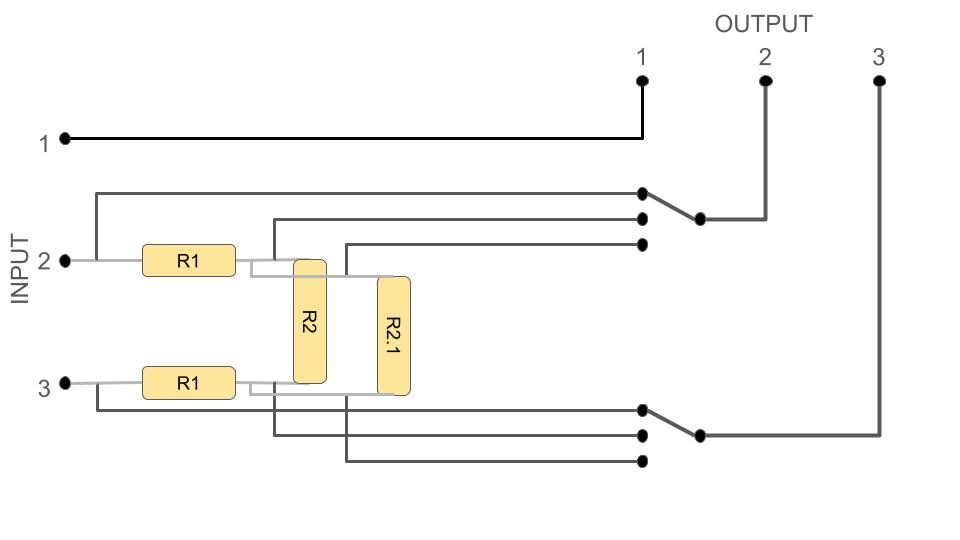
Q3. Any feedback on this? Is it correct?
The switch, if I got this right, would have to be a DPDT On-Off-On toggle switch. Trying to understand the signal flow, for example in pcrecord attenuator pins 2-5 are used as outputs, while 1-4 and 3-6 as inputs for the different settings (attenuation and bypass). If this is correct, the only thing I’m mostly unsure about is how to get the bypass wiring right when 2 attenuation settings are already counted for. So far, this is where I landed:
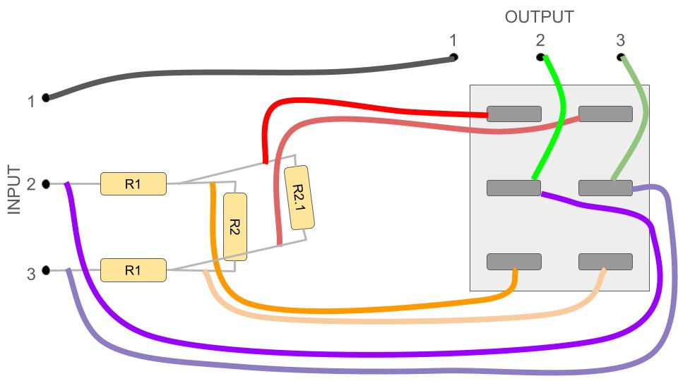
Q4. Do the Bypass wires (PURPLE) create a feedback loop when the switch is ON? If yes, do I need another switch to cut the bypass signal while using attenuation? Or would anybody know a better way to wire the bypass altogether?
Q5. This might be a bit basic, but should the orange and red wires be connected to R1 legs before the R2 connection (like the picture above)? Or after R2 (like in the picture below)?
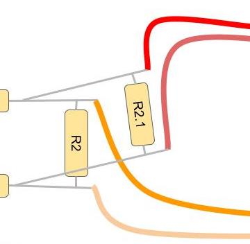
From pcrecord’s video1 the wires seem connected right where R1 and R2 are joined so I’m not certain if there’s a correct way other than making sure the soldering is done on R1 legs and not R2.
This is all I've got so far. Any help as usual would be greatly appreciated!
Hi Giulio,You are in danger…
Hi Giulio,
You are in danger of making this overly complicated. This is partly because you are referring to Marco's solution to his problem, which is not quite the same as yours.
Your diagrams appear to have a 3-position switch that has contacts in the centre position, which standard ON-OFF-ON switches do not have. In addition, the two alternative shunt resistors are permanently connected in parallel in your diagrams, meaning there is no difference in attenuation between positions 2 and 3 on the switch (position 1 being the 0dB position).
The final thing is that you are mixing resistor values that apply only to the + or - leg (R1) with those that bridge the differential signal (R2 and the pre-amp output resistance). The bridging resistor values either need to be halved when used in formulas for attenuation and impedance, or R1 needs to be doubled (effectively including both R1 resistors in series).
SoundSkulptor giving you a value of 66 Ohm for the value of the pre-amp differential output impedance makes things easier, in that we can use the simple attenuation formula that assumes the pre-amp has a zero output impedance and the interface an infinite input impedance. The only concession we might need to make is to reduce the R1 values by 33 Ohm to account for the resistive division ratio. This will give sufficient accuracy for the purposes we are discussing.
In the simple scheme, you use the switch to select alternative values for R2, with the centre (OFF) position giving 0dB (minus a little). See my post of 12 December. The two input resistors (R1) are nominally 1.5K Ohm each, and the switched shunt resistors (R2) are 3K Ohm and 1K Ohm, giving 6dB and 12dB attenuations respectively. If you want to account for the 66 Ohm output impedance of the pre-amp, you could either use 1.47K instead of 1.5K input resistors (impractical), or put 33K resistors in parallel with each 1.5K resistor.
Once again I can't thank you…
Once again I can't thank you enough for the clarifications and your patience.
I have been overcomplicating things for a while unfortunately. I have also been reading books trying to learn more theory behind these components and circuits, but I'm not finding these to be very helpful when it comes to the practical side of things.
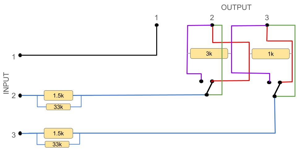
I've made new diagrams so that the switch alternates between the 2 shunt resistors. I've added all resistor values as well as 33k parallel resistors for the input. From all the research and from reading your answers about 3 or 4 (hundred) times, this is what I've understood. Is this how the resistors must be connected?
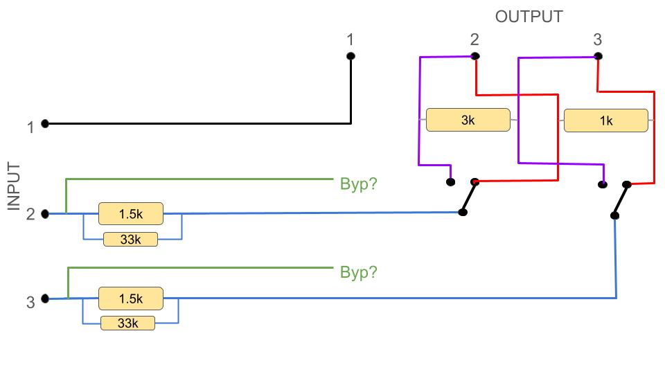
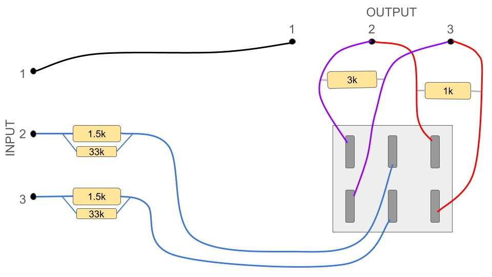
As you might see, I still don't get how the bypass signal would have to go through when the switch is OFF (centre position). Is it that the leg resistors don't apply much attenuation by themselves and that same signal is used as bypass? So connecting switch pins 2-5 straight to the output (like the green wires in the diagrams just below)?
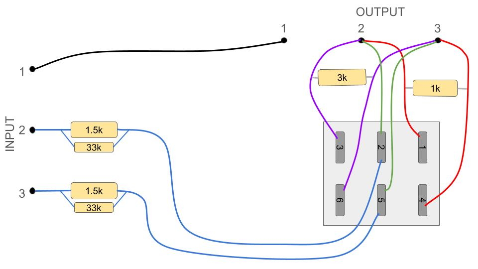
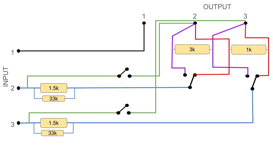
If this is correct then great! But if this is wrong because the OFF position on the switch actually cuts the signal, then the only thing that makes sense to me is to add a DPST On-Off switch on the bypass signal, so that once the attenuation switch is off I can manually let the bypass signal in (following diagram below). However from Boswell's explanation, that seems unnecessary and a DPDT on-off-on would be enough, but again I'm confused on how this would be connected for the bypass section. Any further help would be really amazing thank you!
In addition, calculating the…
In addition, calculating the Total Resistance at each input leg with a 33k parallel resistor, I used the formula:
1/Rt = 1/R1 + 1/R2 = 1/1500 + 1/33000 = 0.000696969
1/Rt = 1/0.000696969 = 1434.78 Ohms
Does this mean we are considering 66 Ohm for each leg? I ask because with a 1.47k resistor instead of 1.5k (without input parallel resistor) we would take approx. 30 Ohm from each leg, summing to an overall 60 Ohm, but with the parallel 33k it's roughly 66 Ohm on each leg, so total 132 Ohm. I noticed instead that calculating the same but with two 66k Ohm parallel resistors, we take approximately 33 Ohm from each leg, summing to roughly 66 again. Is that not what I need? Or am I missing something again and should just shut up and trust Boswell? I am one to question things a lot but more to understand than for lack of trust
EDIT: when I use 1434 Ohm to calculate attenuation in dB it all fits perfectly, but rationally speaking my brain does not comprehend it. And I'm happy that I'm even able to only verify how it works, without understanding the actual logic behind it (for now).
dB1= 20log(3000/(3000+2868) = - 5.82 dB
I then calculate the attenuation considering only the 66 Ohm and no leg resistors
dB2= 20log(3000/(3000+66) = - 0.18 dB
Added together they make a perfect - 6 dB
When instead using the 1000 shunt resistor value the attenuation ends up being approximately -12.25 dB, which is still closer to -12 than if I had 66k input parallel resistors (which ends up being -12.44dB). So if I'm not making this up then I've kind of answered the question.
Thank you once more if you find the time to answer any of this
It's all a lot simpler than…
It's all a lot simpler than you are trying to make it. A single SPDT centre-off (SPDTCo) switch is all you need, as you don't have to to unhook both ends of the shunt resistor (R2). As an aside, I'm using a small "o" in "Co" to mean centre-off, where a capital "CO" would mean "changeover", as in DPCO.
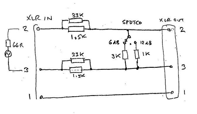
With the values of the resistors you are experimenting with at the moment, you will get a small attenuation (~2dB) in the OFF position, as the 2x 1.5Ks will react with the 10K input resistance of your RME interface. Don't worry about that for the moment, as there are two more stages in the design process.
Once the simple U-pad is working, you can try a variable resistor (e.g. 2K Ohm) across pins 2 and 3 of the input, and experiment with the sonics of loading the pre-amp output down from the ~4K Ohm of your prototype attenuator to the 600 Ohm that the manufacturers designed for. If you like the result of that, measure the pot at your chosen favourite position, and we can scale the attenuator resistor values so that it has a similar input resistance, removing the need for the pot. It will result in the centre-off position of the switch giving much less than 1dB attenuation.
Regarding the parallel 33K resistors, you are probably correct in your calculations, as I was doing them in my head. But it makes little difference, as the end result is to re-work for 600 Ohm (see previous paragraph).
Wow thanks this is…
Wow thanks this is enlightening for me. I really struggle to intuitively come up with the best logical solutions but now I see how much simpler it was meant to be. I've redone the schematics and wiring diagrams but I'll stop cluttering this thread until I'm at a more concrete stage.
It would be ideal to get the 3 settings with one switch and almost perfect bypass, but to be honest in the second stage of the design I didn't quite understand the methodology. I'm good with putting a 2kOhm 2gang pot at the input of my attenuator (before resistors, after the preamp outputs) so that it interacts with my preamp output. Would this be linear or logarithmic taper?
I then experiment with the preamp output and the 2k pot levels, until I match the input resistance of my attenuator to the resistance of the preamp output? Am I trying to match the 0 position on my preamp output to whatever 2k pot value gives me 0 resistance on my attenuator input in bypass position? Or since you said "experiment with the sonics", is my favourite position (that I would measure) based on my taste regarding the sound? Also where is the 600 Ohm coming from? Cause we now know the preamp output is 66 and reviewing past answers we didn't mention 600 Ohm other than for that assumption. I do get the final objective, but I'm quite confused on that whole passage.
And since I don't expect you to indefinitely lecture me on this stuff, I keep thinking that I've gone in way over my head, but also still don't give up. So unless I study well enough, or unless someone as generous as you helps me understand that process, I'm considering to compromise, either keeping the ~2dB attenuation in centre position (might find a use for it) and unplug for true bypass, or just have an on-on switch for shunt resistors and a separate on-on switch for bypass (bit of a waste I know).
Anyway I'll try getting some attenuation working to start with, this is already huge progress, thank you again.
It's probably best to get…
It's probably best to get the stage 1 attenuator set up and working before going into the details of stages 2 and 3. You may decide that you don't want to go on from stage 1.
What I can say about stage 2 is that whenever I do this sort of sonic test, I use a linear pot as a rheostat (2 terminals only) connected across the secondary of the output transformer in the piece of equipment I'm testing (or reviewing). This allows me to vary the loading on the transformer and listen to its behaviour when transitioning from linear operation into the region of magnetic saturation. Some gear comes to life, some gear goes to pieces.
That sounds very interesting…
That sounds very interesting and much clearer, thanks, but definitely beyond my reach at this stage. I will study this aspect more and then decide once I've got the simple attenuator working; hopefully I will have gained more insights in the meantime!
I've ordered the components so hopefully in a couple of weeks I will have a working prototype and some attenuation going.
Boswell you are a legend, I couldn't do this without you, or if I could it would have taken me another 3 months just to figure out the simple stuff.
I truly appreciate it, thank you


My tastes have evolved some over the years. pcrecord, post: 461
My tastes have evolved some over the years.
Oh yeeeeeaaaaaa
Totally. From what i understand they chose the lundhal xformer, specifically because it's one of the cleanest xformers available. Plus if you consider the isa was made for a console, with eq and compressor, it makes sense that its cleaner with tons of headroom. The ISA is one of those pres that just sounds right imho.
I would be curious to hear the attenuator in series, just to hear how the isa saturates.