Hey guys, instead of calling it bad luck, I'm calling it an opportunity to learn.
I scooped one of those "beginner all in one" guitar / amp kits a couple days ago, where the whole thing is in a box, with picks etc etc. It's a first act brand and was $85 total.
The guitar is surprisingly decent (for the price) and even the strap pins on the guitar are wide enough to hold the economy strap decently.
Anyway about 90 second into playing it with the amp the signal faded out, was weak, then absent. No loud clicks or pops. My first guess is the generic thin black cable that comes w every guitar, and are known to be DOA.
I don't have another cable to try, or a 1/8" to 1/4" adapter to try playing a phone thru the amp. I do have a basic multi meter which I don't really know how to use but have to learn as I get into the electronics side of things. I don't own a cable tester either.
I did remove the cable from the guitar jack, and tap it on the metal part of the jack, and it made a buzz when it was contacted, and was quiet when it was touching.
I got the little rig becuase my other guitars are in need of some repair, and the amp runs on batteries, which I want for camping and bonfires, bycycle trips, etc. That gives me a completely battery powered recording rig w either my phone or laptop/Scarlett solo.
Anyway, thanks for any help and suggestions, I'm looking forward to getting on with learning about electronics hardware design and mods. Repairs aren't my fav, but necessary.
Tags
Comments
The way you described the signal "fading out" seems to point to
The way you described the signal "fading out" seems to point to the amp. I'm stressing the word "seems" here because it may not be.
Usually, Cables and jacks, if there are shorts somewhere, will crackle, and intermittently cut out, or pass ground hum.
These shorts don't usually "fade out", they're generally passing the signal, or cutting it off.
I'm assuming - because of the inexpensive price - that the guitar probably doesn't have active pickups - but it was worth checking with you. If it has active pups, the 9v battery might need replacing.
Are you sure that the battery powered amp has good, fresh batteries? Did the amp also come with a power supply that you can use standard household current?
What exact type of batteries are you using in the amplifier? My
What exact type of batteries are you using in the amplifier? My guess (as an engineer) is that it's a battery internal impedance issue.
A friend of mine who has a battery amp labelled "15W" that he uses for busking has said that fading out, particularly after a loud chord, is a symptom of his trying to get away with using the of wrong type of battery.
I would try connecting your digital multimeter on a d.c. voltage range across the battery terminals and observe (a) what what happens to the voltage immediately on switch-on after being off for an hour or so, and (b) after stabilisation in the quiescent state, what the terminal voltage does when you play a guitar chord.
The output power ratings for most dry-cell battery amps are a joke. The amps that are designed to take motorcycle or caravan sealed lead-acid batteries are a much better bet, as at least those batteries do not tend to have such a huge rise in their internal impedance as they discharge.
dvdhawk, post: 452102, member: 36047 wrote: Let's go, time to
dvdhawk, post: 452102, member: 36047 wrote:
Let's go, time to take 15 minutes to learn what to do with it. What are you waiting for?
Lol a link or something telling me how to do it. I literally am completely green when it comes to them and elecrincs repair in general. Any of the classes I've watched online (Stanford/MIT) are all theoretical.
That's actually the first thing I wanted to learn was how to test the cable w a meter. I've been looking to learn this stuff since I got facinated at Zeltec a few years ago. The time is now.
It's passive pickups on the guitar, which actually stays in tune surprisingly.
I'm not sure if the batteries are fresh. It runs on 2 x 9v batteries that were sealed, and included with the kit.
Guitar jack firm.
For the sake of it, let's assume I have no access to my Interface or a new cable, becuase in reality I don't right now, long, long story. Basically I have to work with what's in the kit and my meter. I've also got electrical tape, wire cutters, and I could snag a couple new batteries if needed, but I'm very limited at present.
This amp has individual 9v battery compartments, on the back of the amp, one on the left one on the right.
I'm guessing when i do the procedure you described I should have then batteries connected? (Sorry, I wasn't kidding when I said I'm green w the hands on electrical)
Thanks again guys. Appreciate your thoughts and patience.
This is the one, tho the link isn't greatly informative. https:
This is the one, tho the link isn't greatly informative.
https://www.target.com/p/adam-levine-by-first-act-electric-guitar-pack-al223/-/A-14238148
If I remember correctly it's a 2w amplifier. And didn't include the 14v DC power adapter, which is its alternative power source.
The pack isn't even listed on the first act site, so I'm guessing it's some sort of licensing thing they did with the major retail chains here in USA
Either find a nice clear image of your meter on images.google.co
Either find a nice clear image of your meter on images.google.com or take a good, clear, well-lit photo and post it in a size big enough we can read the settings. Seriously... 15 minutes. It will take me longer to type than it will for you to learn the 3 main things you'll want to know how to measure with it.
I would be happy to help you get that multi-meter-monkey off your back. In just one easy lesson you'll be making moves like Jagger with your meter. Impress the ladies, amaze your friends, be the life of the party, earn tens of dollars...
dvdhawk, post: 452126, member: 36047 wrote: Either find a nice c
dvdhawk, post: 452126, member: 36047 wrote: Either find a nice clear image of your meter on images.google.com or take a good, clear, well-lit photo and post it in a size big enough we can read the settings. Seriously... 15 minutes. It will take me longer to type than it will for you to learn the 3 main things you'll want to know how to measure with it.
I would be happy to help you get that multi-meter-monkey off your back. In just one easy lesson you'll be making moves like Jagger with your meter. Impress the ladies, amaze your friends, be the life of the party, earn tens of dollars...
I very much appreciate it sir. I'll gladly throw something in the tip jar for your time.
When it's light out tomm, I'll take a photo w this iPhone. I'm happy to put in as much time as it takes, and do anything I need to do as far as reading or whatever on my own as well. I seem to have nothing but time suddenly. I'm looking to become somewhat proficient at this end of things. Enough to modify and build basic things, and have some sensibility with my more grandiose designs as I pass them on to cats like boz and dan, to bring them to life.
Your time and patience is really appreciated man, hopefully I can return it somehow.
kmetal, post: 452112, member: 37533 wrote: This amp has individu
kmetal, post: 452112, member: 37533 wrote: This amp has individual 9v battery compartments, on the back of the amp, one on the left one on the right. I'm guessing when i do the procedure you described I should have then batteries connected? (Sorry, I wasn't kidding when I said I'm green w the hands on electrical)
Yes, measure under load, although you could do a preliminary step of taking the batteries out and checking their open-circuit terminal voltages, as your symptoms could be caused by having one OK battery and one dud. Just recently I had a malfunctioning doorbell where the four internal batteries were connected in series. Taking them out and measuring them showed one battery had a negative voltage, as it was faulty and being overdriven by the other three. Are the batteries in your amplifier PP3 or some other size?
Thanks again fellas. I'll start w a photo of the type of batter
Thanks again fellas. I'll start w a photo of the type of battery, I'm not sure if it's pp3, but it looks like this, and what I would call 'a standard 9v battery'. My usual method of test these is to touch both contacts to my tongue to see if there's charge. lol I'm guessing there's a more relaible and accurate way...?
I hope the snapshot of the meter is clear enough, when I used the flash it was actually more difficult to see due to glare/reflections. I've included the screenshot of the stock photo and link from where I purchased it for reference.
https://m.harborfreight.com/7-function-multimeter-98025.html?utm_referrer=direct/not provided
Mucho Gracias.
Fwiw that particular store gives these away free with any purcha
Fwiw that particular store gives these away free with any purchase sometimes as part of a promotion they run, which gets you in the store in person, and in my case buying more than I went for lol.
So if I need something better or more sophisticated I can probably get one, since I have a bunch of things I'm returning to the store in the near future. I'll also have credits at the Home Depot and lowes, if they stock what I need.
This meter will be all you need to get started, and significantl
This meter will be all you need to get started, and significantly more accurate than your tongue.
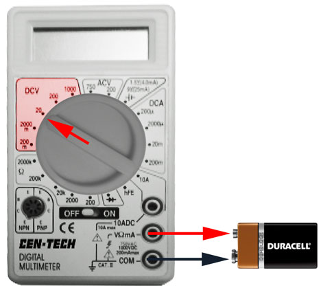
Alright, let's test the voltage of those 9V batteries with them removed from the device. If you do it this way the voltage displayed is the voltage while the battery is not under any load. In other words, the reading is unrealistically high compared to what it will be while it's doing any work. Either way, this is a good place to start. For reference a brand new alkaline 9V by Duracell or Energizer will read about 9.85V and a new AA will read about 1.65V without a load. Boswell wants you to take readings with them under load (installed and the amplifier working), but let's start by testing them free from the amplifier.
Step 1: Plug the black probe into the COM (Common) and plug the red probe into the middle jack V (because you're measuring Voltage)
Step 2: Since your meter does not automatically set a range you will have to select one manually.
This is easy because you know the battery is 9V DC. So in the upper left of the dial there's the DCV section, set it to 20V (more than enough to read a 9V battery).
If you set it too high, say 1000v, your reading won't be as accurate. If you set it too low, you may find yourself going back for another meter, or changing the internal fuse it's likely to have. If you're unsure of the voltage on something set it at the highest setting (1000V) to get a rough idea and then range down to it.
Step 3: Turn the meter ON, and hold the black probe to the - terminal (the wider of the two) and the red probe to the + terminal of the battery (the narrower of the two).
It may take a few seconds for your display settle on a voltage. In this case since it's DC, you can reverse the probes and get a negative number - no harm done.
You'll want to get in the habit of keeping your fingers clear of the probes and terminals. A) you don't want to develop any shocking bad habits that may bite you when you measure things with higher potential of killing you. And B) you're a semi-conductor, although you're not a very good one, you can skew the readings.
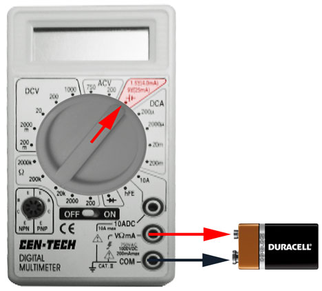
Alternate Step 2: Your meter provides a handy little Battery Test Section in the upper right corner. This drops a resistor across the + and - and puts a little load on the battery. Now instead of it displaying voltage, it will display milliamps. They say 25ma is a normal reading for a 9V, and 4ma is a typical AA reading.
Again, this is all very safe battery level DC. (You can safely stick it on your tongue)
Back later with cable testing and AC voltage.
Make sure you turn the meter OFF when you're done. Some of these cheapo meters use oddball batteries that can be expensive (relative to a $6 meter).
Thank you so much, this explanation deserves a sticky. Exactly
Thank you so much, this explanation deserves a sticky. Exactly what I was looking for, a step by step by a reliable person. I will do this when it's light out, in the next day or two. If I can I'll film it or at least take some photos. I just wanted to thank you ahead of time. I appreciate not just the how, but the why as well. Excellent.
OK, next you've got a guitar cable (or mic cable) to test. Step
OK, next you've got a guitar cable (or mic cable) to test.
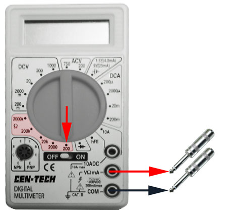
Step 1: Plug the black probe into the COM (Common) and plug the red probe into the middle jack Ω (because you're measuring Ohms). Just about everything you're going to want to do will have the red probe plugged into the middle jack. The black will always be the Common.
Some meters have a separate "Continuity" setting, which makes an audible beep when you've got continuity (virtually zero ohms). This saves a lot of time testing a patchbay or something, because you don't have to take your eyes off the probes while you listen for the beep.
Step 2: Since your meter does not automatically set a range you will have to select one manually.
This is easy, because you know a working instrument cable will have 0Ω (zero ohms) or darn close to it from Tip to Tip and Sleeve to Sleeve. In the lower left of the dial there's the Ω (ohms) section, set it to the lowest setting, which on your meter is 20oΩ.
If you set it too high, say 2000k (2 million ohms), your reading won't be very accurate, but it should still be OK for cable testing. We don't really need much accuracy for this job. If you ever set it too low, for instance, set it to 200Ω and try to test a 1000Ω resistor, it will just read out-of-range, by displaying a "1" on the left-hand side of the LCD, not followed by any other digits. No harm done. This "1" is normal and that's how it indicates the reading is out-of-range and this is something you need to be able to recognize for the next step(s).
Step 3A: If the probes aren't touching each other when you turn the meter ON, and its set to any of the Ω settings the meter should read "1" indicating it's out-of-range (with the probes NOT touching you'll have infinity ohms / no contact / no continuity). Now to see what good continuity looks like, touch the black probe against the red probe to make sure everything is kosher. If you've set it anywhere in the Ohms section, shorting the leads together should give you a reading of 0Ω (zero ohms) or darn close to it. Separate the leads and the display will go back to its out-of-range display (infinity ohms). Touch them together, and separate them You are making and breaking contact, just like a switch. Open, Closed. Open, Closed. Repeat until bored.
Step 3B: Now back to testing your guitar cable. Take your 1/4" cable and hold one probe on one of the Tips, and the other probe on the other Tip. If the connector and cables are good, it should give you a reading of 0Ω (zero ohms) or darn close to it**. Repeat this for the the Shield to Shield reading, again you should get close to a zero reading.
Step 3C: **A step that is often overlooked. Let's say you got a zero ohm reading Tip to Tip, and a zero ohm reading Sleeve to Sleeve. That's good right, but does that guarantee the cable is going to work? Not necessarily. So it's here I would test Tip to Sleeve on either end, to make sure the Tip and Sleeve aren't shorted together somewhere. The first part of the test establishes that there aren't any open contacts (broken wires, or solder connections), but this part insures there aren't any shorts across the two conductors. And with 1/4" connectors the thin insulator inside the metal shell can get damaged or rub through over time causing a short.
This same methodology applies to TRS, just test the Ring to Ring in there somewhere.
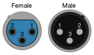
If it's an XLR, just stick a probe down into pin #1 on the female end, and hold the other probe to #1 on the male end, making sure you don't touch the metal shell, or any other pins at the same time. Don't forget that when you're looking at the end of an XLR their pinout is mirror-image male to female.
Test them in any order, it doesn't matter. Usually while I've got one probe in the #1 female, I'll check all three pins on the male side F1 to M1 / F1 to M2 / F1 to M3 to make sure there aren't any shorts. You obviously want continuity F1 to M1, but not F1 to M2, or F1 to M3. Then move the probe to the #2 female and test against pins #2 and #3. If you make it this far without any cross-shorts on #1 or #2, then you've eliminated all the other combinations and just testing #3 to #3 should be sufficient.
On XLR and TRS connectors especially, if you find a problem and get a pin that reads out-of-range, then testing across all three pins will also tell you if some soldered an end wrong (say they swapped 2 and 3, or forgot about the mirror image thing and soldered F2 to M1, F1 to M2.)
Again, you'll want to get in the habit of keeping your fingers clear of the probes and terminals. A) you don't want to develop any shocking bad habits that may bite you when you measure things with higher potential of killing you. And B) you're a semi-conductor, although you're not a very good one, you can skew the readings. In fact, for this one, you can set the meter to its highest ohm range and just pinch the probes very firmly between your fingers and probably get a reading.
Turn the meter OFF when you're done. See previous post.
The last installment of Metering 101. ** This lesson is specif
The last installment of Metering 101.
** This lesson is specifically for Kyle, since I'm confident in his judgement and abilities to master this skill. Anyone else who chooses to start poking around in high-voltage devices does so at their own risk.
Ok Kyle, hopefully you've managed to not electrocute yourself thus far testing 9V batteries and guitar cables, well, here's your big chance. So put down your phone for a minute and pay attention. There is a very minimal, but very real risk involved here testing high-voltage things. It only takes a momentary distraction, or split-second of carelessness to get yourself shocked - or worse [including, but not limited to: death, loss of a finger, sparks and/or catastrophic fire]. So with that as a standard disclaimer and a stern word of warning. Proceed at your own risk. If you don't feel comfortable enough, or confident enough to attempt this, DON'T! You can walk away with Lesson 1 and 2 in hand, knowing your meter is a great battery and cable tester.
OK, Kyle. If you're sure you are up to it. (I wouldn't be coaching you through it if I didn't think you could handle it.)
Focus...
Deep Breath...
Step 1: Check to make sure you're not wearing any dangling metallic jewelry that could accidentally, and unpredictably, come in contact with the outlet or the exposed part of the probes. Most electricians will remove their wedding band and anything else metal when working around high voltage, but at this level of testing you should be safe leaving on a ring unless you're deliberately trying to get shocked. If you've got any other piercings, I'd rather not know about them, but you'll have to use your own discretion.
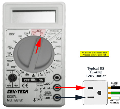
Step 2: Plug the black probe into the COM (Common) and plug the red probe into the middle jack V (because you're measuring Volts again). Double-check that they're fully inserted so the insulation is seated snuggly against the meter and be sure that there is no exposed metal showing between the meter and the test leads. *It didn't matter very much testing batteries, but the stakes are a little higher now.
Step 3: Since your meter does not automatically set a range you will have to select one manually.
This is easy, because for this test you know the voltage on a standard US wall outlet is 120V. In the upper section of the dial there's the ACV section, set it to 20oV.
Step 4: On a typical US 120V 15-amp wall outlet each receptacle has 2 slots and a D-shaped hole.
One slot is HOT (120V when measured to ground)
One slot is NEUTRAL (theoretically 0V when measured to ground)
and of course the D shaped hole in the middle (in theory) should be the Earth GROUND itself.
All modern buildings would have to be wired with proper grounding to pass inspection. Some older homes may have 3-prong receptacles installed, but still be ungrounded, because they use the old non-grounded 2-conductor wiring to power them - because totally rewiring an old house is a major project.
You'll notice that one of the two slots is smaller than the other. And IF (HUGE IF) the receptacle is wired correctly:
The smaller slot is the HOT
The wider slot is the NEUTRAL, (if it's a 20-amp receptacle the NEUTRAL is T-shaped.)
If you carefully stick one probe in each of those slots (making sure your fingers don't touch the metal part of the probes, and making sure the metal part of the probes don't contact each other) you should get a reading somewhere near 120v. You should feel the probes slide between the two contact blades inside each slot, and they will usually hold the probes in place once inserted.
AC has no + or -, so it won't matter which probe goes in which slot, the reading will still be a positive volt (where voltage exists).
If you get a 0V reading here, either the receptacle isn't on, your meter isn't working, or some idiot wired the HOT to the GROUND. More on other testing combinations later. Find a different outlet you know is working and see if you get a reading on your meter there.
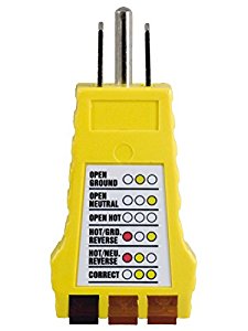
Step 5: OK, so you got a voltage reading hopefully near 120v in Step 4. And if all you wanted was a no-load voltage reading, you can stop there. But again, that's only half the story. What you don't know from that reading is whether the HOT and NEUTRAL might be backwards, or if there's even a working GROUND. I know you have a basic receptacle tester, to do this, but now you can also use your meter to test both of those things in 3 seconds. (since you're already there, meter in hand)
To test for GROUND and confirm HOT/NEUTRAL in one more easy 3-second step, leave the one probe in the smaller slot (HOT) and stick the other in the GROUND, if there's a proper ground wire attached to the receptacle, you should also get the same 120V reading you got in Step 4.
(NOTE* with short skinny probes you may have to feel around the edge of the D-shaped hole of the GROUND until you make contact, there's nothing in the GROUND that will hold the probe in place) Just don't assume if there's a 0V reading the HOT is mis-wired, you may not be making contact with your probe to the GROUND's internal contact yet.
That's it. To review, a 120v reading between the GROUND and smaller slot (HOT) in Step 5, combined with the 120v reading HOT to NEUTRAL in Step 4 confirms both A) there is a good GROUND AND B) that the receptacle is wired correctly, simply by moving one probe from the NEUTRAL to the GROUND. If that all checks out, you're done.
Even if everything else tests OK, you can still put one probe in the wider NEUTRAL slot and the other in the GROUND. You should get a reading of 0V (or darn close to it). It should be zero in theory, but in the real world there is sometimes a very slight voltage present between the NEUTRAL and GROUND for a variety of reasons. (other appliances polluting the power elsewhere in the building, for example).
If you get 120V reading between the HOT and NEUTRAL slots, AND a 0V reading between GROUND and the smaller slot which should be the HOT, it will require a deeper dive because it means one of 3 things:
You're not making contact with your probe inside the GROUND
There is no GROUND attached to the back of the receptacle
or, HOT and NEUTRAL might be reversed
You can confirm, or eliminate, that last one quickly. If you got a 120V reading back in Step 4 and now find a 120v reading between GROUND and the wider slot that should be NEUTRAL, then HOT and NEUTRAL are reversed, but on the plus side, you DO have a working GROUND.
If you find a 0v reading, again, either:
You're not making contact inside the GROUND with your probe
Or, there is no GROUND attached to the back of the receptacle
Without a good ground wire to reference to, there's no way confirm that the HOT and NEUTRAL are correct. You would need an external ground to reference (grounding rod, buried metal water pipe, etc)
Turn off your meter.
OTHER IMPORTANT NOTES:
Don't forget that in Audioland, it's common to use cables with white and black conductors, with the white being positive and the black being the negative. But if you're looking at the backside of a standard US receptacle or connector in Electricianland, white is the theoretically harmless neutral and black is carrying the deadly high voltage. If there's a red wire present, it's probably hot too. BUT NEVER ASSUME ANYTHING WITH HIGH-VOLTAGE. Find someplace to safely ground one probe and use your meter to confirm what's HOT and what's not.
If you go building your own power cables, you may notice that one of the terminals is silver colored and the other is a brass color. You'll want to put the white wire into the silver (neutral) terminal, and the black wire into the brass (hot) terminal. The ground should be pretty obvious, and is almost always green. That's the US standard, but it does vary around the world.
You would use the 750V range for testing a 240V range plug, dryer plug, or beyond - which hopefully you would be doing with expert supervision, until you're further along in your education.
You've seen experiments where someone holds a fluorescent bulb in their hands while high voltage courses through their body to light it up. You can have a million volts safely go through your body if the amperage is sufficiently miniscule. Meanwhile, you can get seriously injured working on a 12V car system using a normal car battery that has 400 amps of power. As the voltage goes up, sometimes the amperage goes up too, but don't presume a lower voltage automatically means no risk.
It's not the voltage that will kill you, it's the amperage that comes with it.
If you've successfully gotten this far without any sparks, any swear words, or accidental welding going on, don't get cocky and start poking around in breaker panels, old TV sets, tube amps, etc. without one-on-one expert supervision. There can be seriously deadly power in those things - even if something has been unplugged for a long time. Those soup can size capacitors in a Marshall amp hold that 600v charge a long time, ask me how I know...
Those defibrillator paddles you see them use on TV, don't jump-start your heart. They stop it, so the medics can restart it with a normal rhythm.
NEVER ASSUME ANYTHING WITH HIGH-VOLTAGE, and since you have a meter, and are learning how to use, it you don't have to assume. Find someplace to safely ground one probe and use your meter to test what's HOT and what's not.
Be careful out there. Class dismissed.
As an electrician I will add one thing to this most excellent re
As an electrician I will add one thing to this most excellent repartee' on the testing with a multi meter. The "white theoretically harmless neutral" is not always harmless for many reasons. The best and quickest explainin for that situation is it being a live circuit and having a load DOWNSTREAM from it on the same circuit. Any time there is demand from any point in a circuit, there is going to be some "return load" able to be measured and if you happen to be between the 'grounded' (neutral) conductor and the 'grounding' (earthed) conductor, you will get shocked from the feedback on that circuit. And don't even get me started on the old practice of multi-wire circuits that shared neutrals. Just be careful.



Obviously, the first thing to check is the cable. It's part of t
Obviously, the first thing to check is the cable. It's part of the process of elimination - starting with the easiest and most common problems.
If you get a new cable and it still doesn't work, then there's either an issue with the amp or the guitar.
Try plugging your guitar directly into your interface's DI (using a cable you know is good) and if your getting signal, then you've eliminated the guitar as a problem.
It's difficult to say at this point, have you felt the jack input on the guitar to make sure it's not loose? If you move the cable, are you getting intermittent signal flowing and then cutting out?
The amp could be to blame... I'm assuming it's got sufficient power because it's on...
1. Cable
2. Guitar
3. Amp
But until you get a cable you know for sure is good, you can't test the other steps.
;)