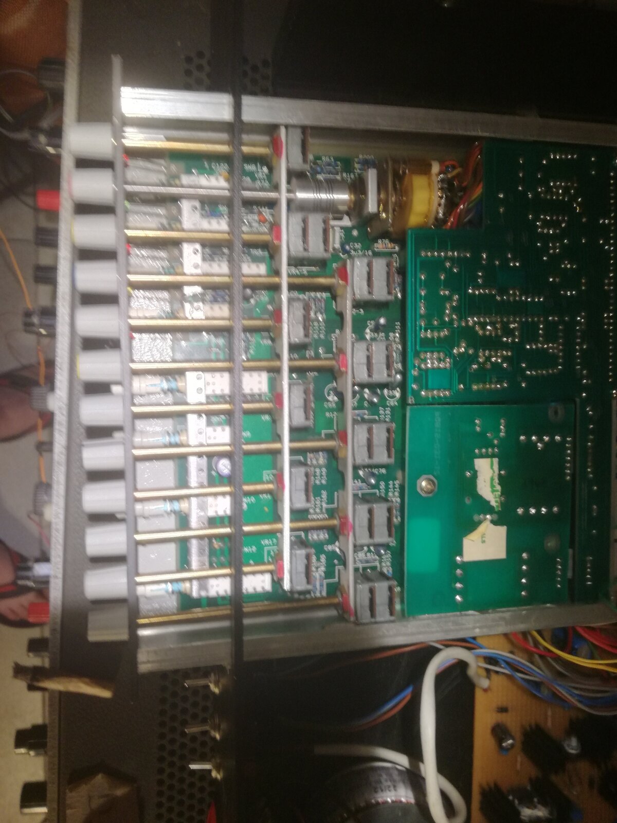
Hello someone Calrec pre / eq PQ2462, I have two modules in a rack to use with condenser microphones, the truth is that they give me a lot of noise when I activate the phantom power. . I would like to find some documentation about them. The pcb is marked as PQ 815-022-9
Thank you
Tags
Comments
I think I should tell you a bit about the state of the equipment
I think I should tell you a bit about the state of the equipment, which I think is faulty for the person who decided to rack mount them.
First of all, the power supply has used a system that I do not like, the transformer only has one winding. With that winding they get + - 16.50 + 5v and with an unorthodox system they get + 43v.
On the other hand, the output signal of the preamplifier is quite low, I suppose because it does not have the master bus of the amplification stage of the original mixer, I want to think that the source gets a lot of noise and when amplifying with the instrument input of a sound card you find a lot of noise, when you use it as a line input the output is low and when amplifying it the same thing happens when you use the microphone input, a lot of background noise.
The microphone part uses an akg 541a, which I also have to put away and well kept so that it does not pick up noise from the street and similar things, but it is also noisy.
At the output of the two preamps apart from having a lot of AC component 50hz 100hz, there is a brutal noise from 200hz to 15,000hz
I think the interesting thing is to change the source and if it can be put out with a transformer that has a winding to get + - 16 another winding for 5v and maybe a separate transformer to take out the 48v. I have no documentation of this preamplifier, it would be nice to know something else , pinout etc..
Saying things like "a lot of noise" is a bit vague. You should s
Saying things like "a lot of noise" is a bit vague. You should separate the measurement of the pre-amp and the microphone.
To test the pre-amp, you will need either a battery-powered signal generator or else a mains-powered generator feeding a 1:1 bal-un transformer used in reverse. The generator should have a switched output range going down to less than 1mV. Feed pins 2 and 3 of the pre-amp XLR input connector from the centre-tapped winding of the transformer, with the centre-tap of the transformer winding taken to the pre-amp ground (XLR pin 1). If you are using the battery signal generator, connect the signal generator output terminals to the XLR pins 2 and 3 and also to a series pair of 1K Ohm resistors, and take the junction of the two resistors to pin 1.
Connect a good-quality multimeter on a.c. range across the output of the pre-amp, plus an oscilloscope if you have one available.
You are now in a position to make some basic signal/noise ratio measurements of the pre-amp, as well as frequency response and maximum output level tests.
It used to be quite common to use a voltage tripler rectifier on the secondary of the mains power supply of an amplifier or a pre-amp for PP generation. One of my early designs worked in that way.


Do you mean (a) that the pre-amp is quiet when using a dynamic
Do you mean
(a) that the pre-amp is quiet when using a dynamic microphone, but activating phantom power (not needed for dynamic mics) makes that output noisy?
(b) the line input is quiet but the microphone input is noisy when PP is on?