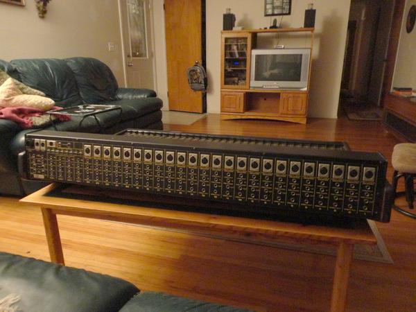
I was just given a Biamp 2442 Recording Console. I am going to have to get the power supply fixed I think. I was thinking about using it as a summing mixer or for its pres since its got Direct outs on every channel. Or just selling it as is for a few bucks. Its in really good shape i mean almost zero wear even the leather hand rest is in perfect condition. It was never used as a touring board but only as an installation at a university. Im having arguments with myself about what to do with it. Its a simple console with not much in the way of routing but i dont need it for that really. It would just be for the pres and summing i think. Ive tried to attach pics to this hopefully they work.
Anyone used one of these and no how the pres sound?
I have all digital stuff right now so this old analog piece of history is tugging on my lust for some serious color in my sound.
Attached files 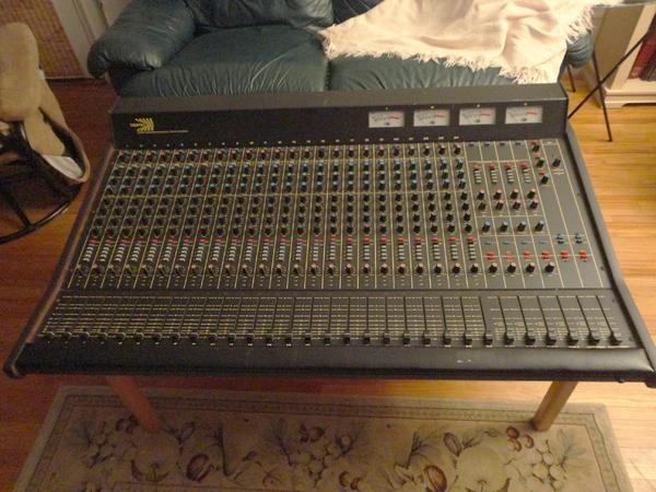
Topic Tags
Comments


These were very good in their day. A quality built and excellent
These were very good in their day. A quality built and excellent sounding mid-range console. The recording boards were even better. At the age it is, you will probably have to replace some caps and such but a refurbished unit like this, even though it wont bring a lot of money as a resale, can bring a lot of sonic pleasure to a mix. The pres arent Neve or API but they arent Tascam or Mackie either.
I mixed a lot of shows at venues with these in place. The EQ's werent as sweet as the big Yamahas but worked enough for live.

Ok im gonna get it going now you have convinced me. I plugged
Ok im gonna get it going now you have convinced me.
I plugged the power supply in yesterday and the light lit so its getting to the light at least. Looks like they took it apart to try to fix it but lost some screws. No biggy there. Ok the bad news. The phantom power light looks to be missing. Also the previous owner cant find the cable between the console and the supply so I might need to make one. Its a multipin so that should be fun. Maybe I can find the ends at parts express or something. If i have guys willing to guide me through this i think i can get this thing running. Im not good at electronics repair but I can follow direction and I can solder so anyone down for walking me through this? I mean I am way bigger than that power supply, I think I could kick its ass. Here is the link to where the schematic is. Its under discontinued products downloads and then 24-28 series mixing console. There are 2 downloads a schematic and a manual. We can do this. [[url=http://[/URL]="http://www.biamp.co…"]Biamp Professional Audio Systems - Downloads[/]="http://www.biamp.co…"]Biamp Professional Audio Systems - Downloads[/]
I don't think the "24-28 series" is the correct manual set for y
I don't think the "24-28 series" is the correct manual set for your mixer. The "42 series" is closer, although the manual and schematic refer only to the 16-channel version. Here are links to the [="http://www.biamp.com/downloads/download_redirect.aspx?ID=213"]Operation Manual[/]="http://www.biamp.co…"]Operation Manual[/] and the [[url=http://="http://www.biamp.co…"]Schematic[/]="http://www.biamp.co…"]Schematic[/].
The operation manual states that the power supply cable has 16-pin connectors. These connectors may be difficult to find if you are contemplating making a new cable. The last page of the schematics gives a wiring schedule for the power connectors but only shows 12 pins. I would check your hardware and see whether they really are 16-pin connectors with only the first numbered 12 wired.
For the 48V PP, don't forget there's a switch on the power supply unit itself.
Your right it is a 42 series board! The power supply says 42 ser
Your right it is a 42 series board! The power supply says 42 series power supply right on it. Thanks for that Bos. Ok the connector has 16 pins. Whats weird is that the consoles connector has 16 and the power supply has 14 total so looks like I will be joining some wires. The connectors pins on the board are indeed numbered. Also the power supply does not have the 48v switch that is supposed to be there. There is a hole for one however. I will need to get a new switch. Yes I understand that I am going to have a tough time finding cable connectors but that just makes this more fun. I was thinking. If i cant find a connector could I just
studio33, post: 384265 wrote: Could I just get a different conne
studio33, post: 384265 wrote: Could I just get a different connector on both sides and rig it that way?
As long the pin-outs on both ends correspond to what they go to internally, theres nothing that says you cant use whatever you want. Be aware that changes like that will make the next person in line for ownership a little queezy. There are still BiAmp parts available. They were in business as late as a couple of years ago although their business was no long mixing consoles. All those parts are still floating around somewhere and someone has privy to them.
We are well on our way. ok ive found the exact parts and will b
We are well on our way.
ok ive found the exact parts and will be able to get them for under $20. Next hurdle is finding the correct value of the switch for the phantom power on the PSU. I have attached the schematic that shows the switch. I need to know what to buy. Will any switch that fits the socket work or do I need a certain value. I have red black and white wires going to the switch. Lastly how long should i make the cable from the board to the PSU? I was thinking 10ft i dont know though is that to long?
Attached files 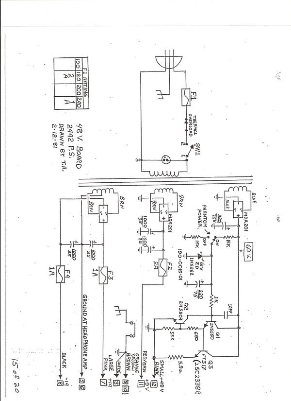
Any toggle switch that fits physically should be OK for the phan
Any toggle switch that fits physically should be OK for the phantom power on/off. It controls a 50V logic signal rather than the actual power line.
As for the length of power cable needed, I would place the console and its power supply in the positions that you would like to have them and then run a vacuuum cleaner hose between the two. Butt one end of the hose up to the output socket of the power supply and then tie a piece of string round the hose at the point where it comfortably reaches the console. Stretch the hose out straight and measure the length from the power supply end to the tape. Add about 6 inches for connector work and you have the length of power cabling needed. Resist the temptation to make it longer than you need.
Well done for locating a source of connectors! Where did you find them in the end?
Im gonna be super honest here. I have 3 wires going to the phant
Im gonna be super honest here. I have 3 wires going to the phantom power switch area(Red Black and White). Not sure how to read that schematic on how to hook it up. If it was 2 wires I would be ok LOL. Any thoughts? I was able to find a part number on the connector thats on the power supply and went from there online and there they were in a warehouse somewhere in Texas i think. Its gonna be less than $15 for both:cool:. I also know that I need to buy a 12 conductor cable but what awg should I use? Buying electronics cable is also something im not well versed in doing.
OK, I didn't know how much experience you had with this sort of
OK, I didn't know how much experience you had with this sort of thing. You need to get an SPDT toggle switch (single-pole, double-throw).
If you can't trace where on the circuit board your three wires originate, you will have to do a trial involving a multimeter. Prepare the ends of the 3 wires so you can momentarily touch two of them together with the power supply turned on. Use the multimeter on 100V range to see which of the wires has the 60V incoming voltage with respect to chassis. Call that wire A and the other two B and C. Only one combination of A touching B and A touching C will turn on the phantom power. Whichever wire is not being connected when the phantom power turns on is the one attached to the resistor to ground. Now turn off the mains power and connect that wire and wire A to the outer terminals of the switch and the third wire to the middle terminal. Mount the switch in the hole in the chassis in what would appear to be upside-down mode, since the toggle acts like a lever with the fulcrum inside the switch.

Hello all, Basically I've been scouring the Internet for the las
Hello all,
Basically I've been scouring the Internet for the last hour to try find an answer about the psu for this unit. I bought it today, second hand, from some fool for £5. He just wanted rid of it.
Very proud
But yeah, it came without a power cable with it, so I've bought it blind and gone out on a bit of a whim.
If anyone could point in the right direction for a replacement not sure if it has a standard fit and has a name for it.
My little mixer has a similar principle, but it is much smaller, so I figured it would be worth the risk.
Thanks.
Luke
Getting there! Bos. Phantom is hooked up correctly. Is it norma
Getting there!
Bos. Phantom is hooked up correctly. Is it normal to be getting less than 48v across a switch like that. I think I read like 36v. Want to make sure my condensers arent going to be under powered. Anyway the readings came out just like you said except for that. Now I just need to know what cable to buy. I have 16 positions on one end and 14 on the other and the schematic is showing just 12 conductors being used. Also I need to know the awg I should buy. The wires on the inside of the PSU that are going into the back of the mounted connector are fairly thin.
Luke go to this link. The schematic for the PSU is in the schema
Luke go to this link. The schematic for the PSU is in the schematic for the board. Go to this link and click on "discontinued product downloads" then go down to the "42 series schematic" vala! Its a downloadable PDF. Cheers [[url=http://[/URL]="http://www.biamp.co…"]Biamp Professional Audio Systems - Downloads[/]="http://www.biamp.co…"]Biamp Professional Audio Systems - Downloads[/]
Thanks. This could be handy. I'm not fantastic with electronics,
Thanks. This could be handy. I'm not fantastic with electronics, but I'll keep it in mind.
Basically, what I was really looking for was a ready to go power lead. As in mains plug, transformer, 16 pin plug.
Or am I going to have as much luck as trying to find the lost arc?
Thanks
Luke
studio33, post: 384769 wrote: Bos. Phantom is hooked up correctl
studio33, post: 384769 wrote: Bos. Phantom is hooked up correctly. Is it normal to be getting less than 48v across a switch like that. I think I read like 36v. Want to make sure my condensers arent going to be under powered. Anyway the readings came out just like you said except for that. Now I just need to know what cable to buy. I have 16 positions on one end and 14 on the other and the schematic is showing just 12 conductors being used. Also I need to know the awg I should buy. The wires on the inside of the PSU that are going into the back of the mounted connector are fairly thin.
Well done on getting this far, but I'm slightly worried by your seeing only 36V on the switch. When the PP is switched off, there really should be something like 60V on the power wire to the switch, unless you are using a very low impedance meter. When the PP switch in in the on position, the 60V should drop to 51V. Have you used the multimeter to check the phantom power on pin 12 of the power supply output connector? It should be between 44V and 52V.
For multi-core cable, you may have to go with what you can get. The important point is that you use power cable and not signal cable, so anything with a conductor cross sectional area of less than about 1 sq mm is not suitable. The company Pro-Power make a large range of multicores, and their CY range looks the sort of thing you would need. This is a screened multicore, and you should connect the screen to a ground pin at both ends of the run.
Bos - Well with my lack of knowledge about testers I think I was
Bos - Well with my lack of knowledge about testers I think I was measuring on the wrong setting. I switched to 300 from 200 and now im getting 48 on pin 12 dead on so that seems to be rockin now. Now as far as the cable is concerned. What site did you find that on? I cant find a 12 conductor cy that I can buy by the meter. Thanks for all the help by the way. This is great being able to learn like this.
I'm glad you seem to have 48V on the output pin. You should chec
I'm glad you seem to have 48V on the output pin. You should check that with the PP switch off the output pin is accurately 0V and not floating around at some indeterminate level. That should confirm that you have the PP switch wired correctly.
As for the cable, I have to apologise here. I have used the Pro-Power CY range from the UK supplier Farnell and know that you can purchase any length up to a 50m reel. I saw also that their US subsidiary Newark had the same cable, but on closer inspection it looks as though Newark will only ship whole reels, which isn't much use to you. The Pro Power make of cable was only an example, so you may have to ask around your US cable merchants to see what they have in the way of similar type of cable.
ok got the connectors and they are the right ones indeed. Exciti
ok got the connectors and they are the right ones indeed. Exciting! Now I still need to get the cable. The techs that I talked to on the phone said they needed to know what the cable needed to be rated at in order to sell me the right stuff. Not sure what that is but. They said that 1sq mm meant very little to them. What (could I tell them based on the schem.. that I need to have.
Well, the schematic won't tell you what sort of cable to get. Be
Well, the schematic won't tell you what sort of cable to get. Besides getting a cable with enough cores (conductors), there are two things to consider: the wire cross-sectional area for its current-carrying capability and the cable outside diameter so that it fits in the strain reliefs of the connectors. I'll leave the second point to you as you have the connectors in your hand.
For the cable choice, I'm amazed that a wire salesman could not tell you what the conductor area was in the cable he sells. Specifying at least 1sq mm means conductors up to about 16AWG, but 12 or 14 would be better. As an example, the [[url=http://[/URL]="http://www.farnell…"]Belden 8622[/]="http://www.farnell…"]Belden 8622[/] series is 16AWG and is specified as 5A per conductor. This is a bit marginal, so you might want to look for 14AWG with the right number of conductors.
I don't see why not. Get some 10A multi-strand single-conductor
I don't see why not. Get some 10A multi-strand single-conductor insulated wire and cut off enough lengths to make up the number of conductors you require in your multicore. The only disadvantage would be that there is no colour coding, so you would have to be very careful to mark the ends of each conductor appropriately.
Bos Im not sure but I think I screwed up. Heres how. I made the
Bos Im not sure but I think I screwed up. Heres how. I made the cable but I didnt do it pin1 to pin1 and so on. I assumed the cross wiring was along the PS Cable. I didnt think that it could be wired 1-1, 2-2 and so on and that the cross wiring of the different colors were inside the PS itself. Could you take a look at the last page of the Schematic and tell me how you would interpret it. I think thats what I did though. Needless to say I got it all hooked up and no signal anywhere ):|
It looks reasonably straightforward, assuming the documentation
It looks reasonably straightforward, assuming the documentation is correct. Ignore the colours given and just use the pin numbers.
The PSU (circular) connector is the left column and the board's Molex connector is the right column:
1 - 2
2 - 1
3 - 3
4 - 4
5 - 10
6 - 11
7 - 9
8 - 12
9 - 7
10 - 8
11 - 6
12 - 5
No, not if the documentation is correct. What you should do is d
No, not if the documentation is correct. What you should do is document the voltages as measured on each pin of the connector on the Molex end of the cable with it unplugged from the console. Make the measurements with respect to the ground on the power supply (not via the new cable).
Not sure what you mean by cable voltage check im not that good a
Not sure what you mean by cable voltage check im not that good at this but I do have a volt meter. I did put 2 fuses in there and they blew right away. Each fuse had a wire going to the PS cable(Pink and Red/Green or pins 7 and 11 are the culprits). I have 3 more of each fuse so no biggie.
That's not very good news. The two most likely explanations are
That's not very good news. The two most likely explanations are that there is at least one fault in the mixer itself that is causing a low resistance on one or more power rails or that the pin connection information is incorrect for your particular mixer.
It would probably not do any more harm to see if replacing just one of the two fuses in turn and powering on results in that one fuse independently blowing.
I have been advised by a guy that looked at the board that the o
I have been advised by a guy that looked at the board that the op amps might need to be replaced. Ive decided to try to fix the board myself. If i screw it up i got the board for free so no loss. Im going to start getting into it this week. Other than that I have another question. I have an old guitar amp and need to find new electrolytic caps for it. They are Mallory uF2500 35v caps. I need to find a suitable replacement. Im worried about buying just any old caps because of tone. what are the best manufactures of stuff like this for audio gear specifically guitar amps.
It depends where those caps are in the circuit. Most probably th
It depends where those caps are in the circuit. Most probably they are used for power supply decoupling, so any equivalent with at least as low an ESR as the Mallory types should be OK. When choosing replacement components, the physical size and the pin spacing are just as important factors as the electrical ratings so I can't give you suggestions for equivalent parts without more detail of the part numbers of the Mallory components.
It could well be that the op amps in the board are damaged. However, replacing them and then connecting up the power supply in its present form may end up with another set of dead op amps. I suggest you sort out the power connctions while the board is still in its present state. This can be done, for example, by continuity testing from op amp power pins back to the power supply connector. Do this before powering up in the morning after the board and supply have been unpowered overnight to allow time for complete discharge of any reservoir caps that still hold charge.

Yup. A very nice console in its day; actually it was considered
Yup. A very nice console in its day; actually it was considered by many engineers to be in the top of its class in that price bracket.. Some said it was a little noisy, but I mixed on one a few times, and I don't recall it being bad enough to be a deal breaker.
The pres were good for the price. As Dave mentioned, they weren't Neve quality, but then again the board didn't cost 100 grand, either. ;)
Good luck on your rebuild, while sometimes difficult and time consuming, sometimes they can be a lot of fun too when you power it up, everything works and you get that sense of achievement.. ;)
I don't know if this would help, and you may already have the link, but you might want to bookmark this if you haven't already:
[[url=http://[/URL]="http://www.biamp.co…"]Discontinued Product Manuals, Schematics and Software - Biamp Systems[/]="http://www.biamp.co…"]Discontinued Product Manuals, Schematics and Software - Biamp Systems[/]
Care to share what your intended use will be?
That was a seriously nice console in its day, albeit not with th
That was a seriously nice console in its day, albeit not with the lowest noise levels. Not many designs in this price bracket had a quality input transformer on every channel.
It would be worth considering it as an effect for a few channels (e.g. vocals), but I would think carefully before putting a 2-track mix though it.
What's the problem with the power supply?