In for a recap and retube and a few modifications. It’s missing the memory module. so it will need some thinking... Looks like a nice build so far..
Attached files 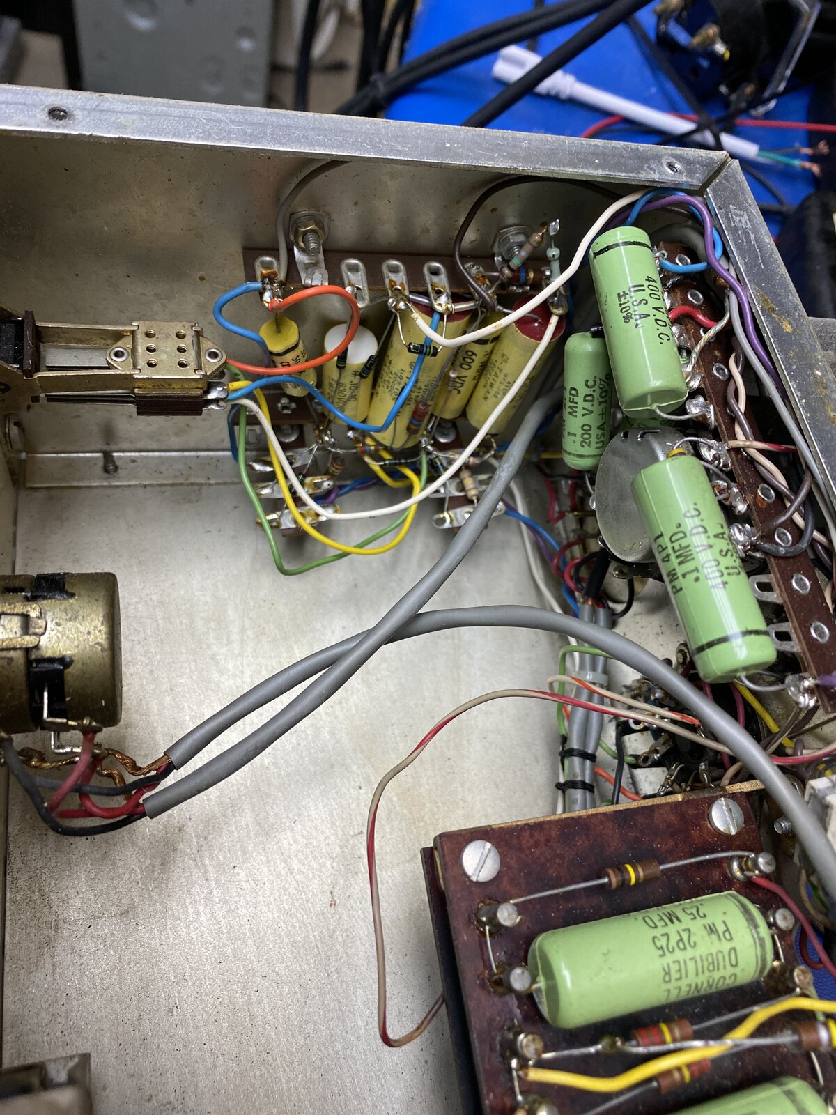

Topic Tags
Comments

I start to look at the JLM mods for this unit... http://www.jlma
I start to look at the JLM mods for this unit...
http://www.jlmaudio.com/forum/viewtopic.php?t=311
A first glance it looks too good to be true. Seems like a simple modification, but I am bit confused on the suggested threshold/attach release controls, I am struggling to see how they make use of V6 (6AL5). I will keep looking...

No idea, but from what I gather it helped introduce the 10 Sec r
No idea, but from what I gather it helped introduce the 10 Sec recovery time constant.
https://groupdiy.com/index.php?topic=914.0
https://www.radioworld.com/miscellaneous/the-cbs-audimax-and-volumax
The unit I have on the desk is not stock it has added switch with some sort of filter circuit, I will need to trace it out to figure what it is doing.

Is this some sort of box that was intended for timing speaker ba
Is this some sort of box that was intended for timing speaker banks in a fixed in place PA system in a hall of some sorts? Many years ago when I was young and relatively stupid, I worked some shows at the Mabee Center @ Oral Roberts U. in Tulsa. They had a center pod and the room was in round. There were banks everywhere and down a manhole walkway was a room full of CBS Laboratories delays, switchers, compressors, companders, etc.... and racks and racks of power amps. Computer floor. 1970's This looks like something from that era
I am struggling to see how the JLM mod works? I am sure he is r
I am struggling to see how the JLM mod works? I am sure he is right, but I can't help but think we has the 6AL5 wired backwards. Does the current flow through a vacuum diode opposite to a regular diode?
To me it looks like he has his positive voltage source connected to the Cathode?
http://www.jlmaudio.com/Audimax II JLM Mod.pdf
What I am missing here?
Attached files 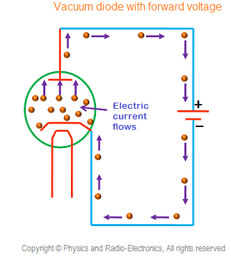
Yes, I read about the supposed origins of the CBS gain control u
Yes, I read about the supposed origins of the CBS gain control units in the groupdiy threads. My guess is that the two different compressors (Audimax and Volumax, for operation in series) were originally designed and built for the US AM radio market. It's then possible that a military comms engineer spotted the products and wondered if they would work in the appalling acoustic conditions found inside a tank. He approached CBS Labs, who responded by adapting the threshold levels and time constants for those conditions. I still shudder at valve (tube) products being used in critical applications inside the first large passenger aircraft, let alone a tank.
Regarding the 6AL5, it's a rectifier, so, in signal terms, a lot of the time the cathode will indeed be more positive than the anode, and this will only reverse for input peaks greater than the threshold. In d.c. terms, the polarity is all down to what's inside the "memory unit" plugin. If that is unchanged from an original CBS potted unit, pins 3 and 9 are not shown with any connection inside the compressor, so it's hard to guess at how the wired mod is supposed to work.
I find the CBS circuit diagram hard to follow. It was probably drawn by a graphic artist who made it his job to get everything on one page without any understanding of the way signals should be represented flowing across a schematic.
The Physics and Radio Electronics diagram is about as misleading as you could find. The purple arrows flowing into the anode (plate) and round into the +ve terminal of the power supply are clearly meant to show electron movement, but labelling it "Electric current flows" is opposite to what is normally meant by a current.
Boswell, post: 467077, member: 29034 wrote: Yes, I read about t
Boswell, post: 467077, member: 29034 wrote:
Yes, I read about the supposed origins of the CBS gain control units in the groupdiy threads. My guess is that the two different compressors (Audimax and Volumax, for operation in series) were originally designed and built for the US AM radio market. It's then possible that a military comms engineer spotted the products and wondered if they would work in the appalling acoustic conditions found inside a tank. He approached CBS Labs, who responded by adapting the threshold levels and time constants for those conditions. I still shudder at valve (tube) products being used in critical applications inside the first large passenger aircraft, let alone a tank.Regarding the 6AL5, it's a rectifier, so, in signal terms, a lot of the time the cathode will indeed be more positive than the anode, and this will only reverse for input peaks greater than the threshold. In d.c. terms, the polarity is all down to what's inside the "memory unit" plugin. If that is unchanged from an original CBS potted unit, pins 3 and 9 are not shown with any connection inside the compressor, so it's hard to guess at how the wired mod is supposed to work.
I find the CBS circuit diagram hard to follow. It was probably drawn by a graphic artist who made it his job to get everything on one page without any understanding of the way signals should be represented flowing across a schematic.
The Physics and Radio Electronics diagram is about as misleading as you could find. The purple arrows flowing into the anode (plate) and round into the +ve terminal of the power supply are clearly meant to show electron movement, but labelling it "Electric current flows" is opposite to what is normally meant by a current.
Thanks Boswell, In the JLM mode he removed the Memory module and replaced it with this...
http://www.jlmaudio.com/Audimax II JLM Mod control box.pdf
Adding the above circuit in place of the memory module as per JLMs mods :
http://www.jlmaudio.com/Audimax II JLM Mod.pdf
I think has a max 61.48VDC threshold voltage applied to the R36 and R37 which through R10 and R11 is connected to the Cathodes of Vacuum diodes. Where the anodes go back the center tap of the input transformer. So I am correct in my understanding that any peak above the threshold voltage will be applied to one side of C8 and C9? The other side of the caps essentially tied to the output transformer. The primary center tap of the output transformer is tied to 265VDC?
Oh forgot to include that I inspected the J2 plug in module which shorts 1 to 4 and 2 to 3. This was removed for stereo operation...
I had a better look at the JLM modifications last night. One thi
I had a better look at the JLM modifications last night. One thing I really like about the original CBS design is that it is a fully-differential circuit from input to output, and this means that common-mode points (such as the centre-tap of the input transformer secondary) can be used to set d.c. operation points separately from the a.c. signal passing through. It's a bit like using phantom power on a microphone XLR input.
What JLM have done is (a) unhitch the input transformer secondary CT from ground and make it available to the compressor control voltage, and (b) feed the transformer secondary signals (d.c. coupled) straight to the grids of the 6386 vari-mu triode, bypassing (and removing) the 6DK6 input pentodes. If you look at the transfer characteristics of a cascode-connected 6386 (shown below), you can see how much the transconductance can be made to vary with the first-stage grid voltage. What the JLM mod does is add the control voltage to the signal, so that the gain of the triode stage is controlled by the amount of (negative) grid voltage applied to the input transformer CT. The 6AL5 dual rectifier is wired to produce these negative voltages, which are modified by attack and release time constants in the plug-in box.
Neat.
Attached files 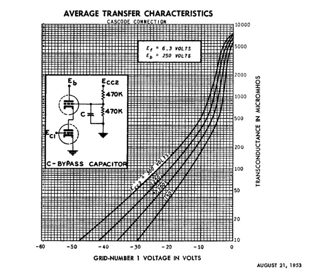
THANK YOU Boswell, that was exactly what I was struggling with.
THANK YOU Boswell, that was exactly what I was struggling with. I was stuck on the negative control voltage for some reason... I really don't know why...most compressors I have seen used negative control voltage... anyway thanks Boswell this really helps!
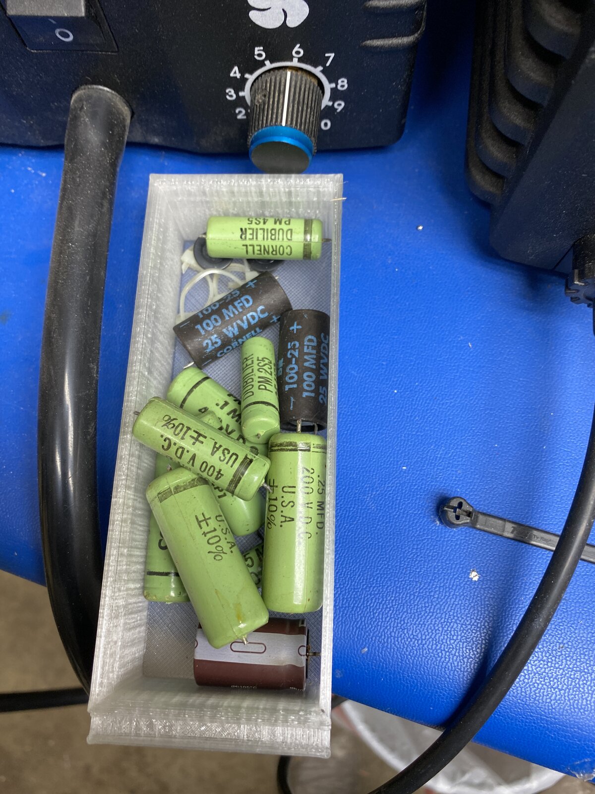
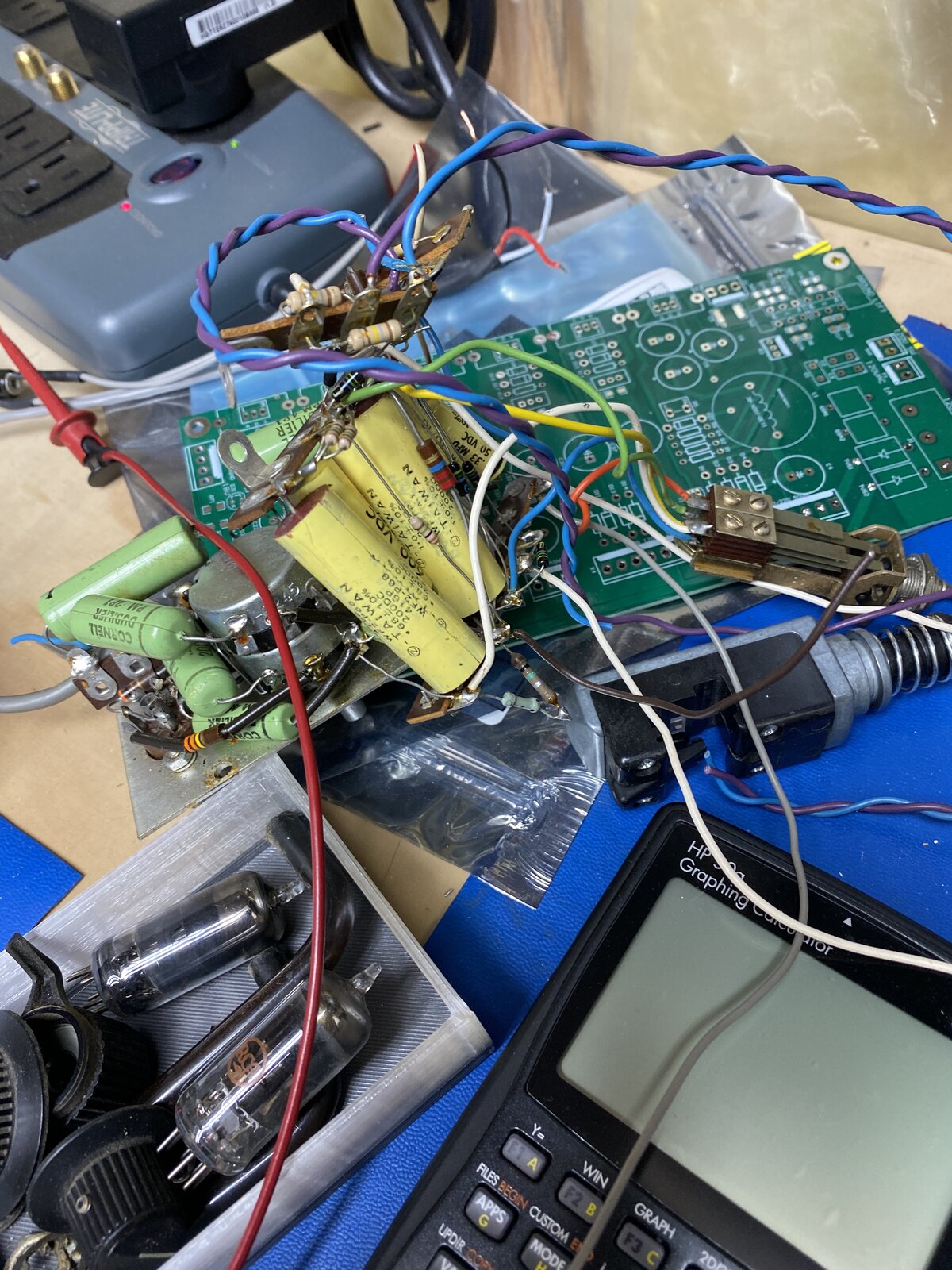
I received the cap and tubes in record time. Ordered Saturday arrived Tuesday...that's quick for my area. Started to sort out the other mods done to this unit. It looks like the last person working on this removed the memory Module and changed the 6386 to a 5670. Then added a switchable set of RC filters to 6AL5 anodes. The yellow caps in the picture are the added filters.
Attached files 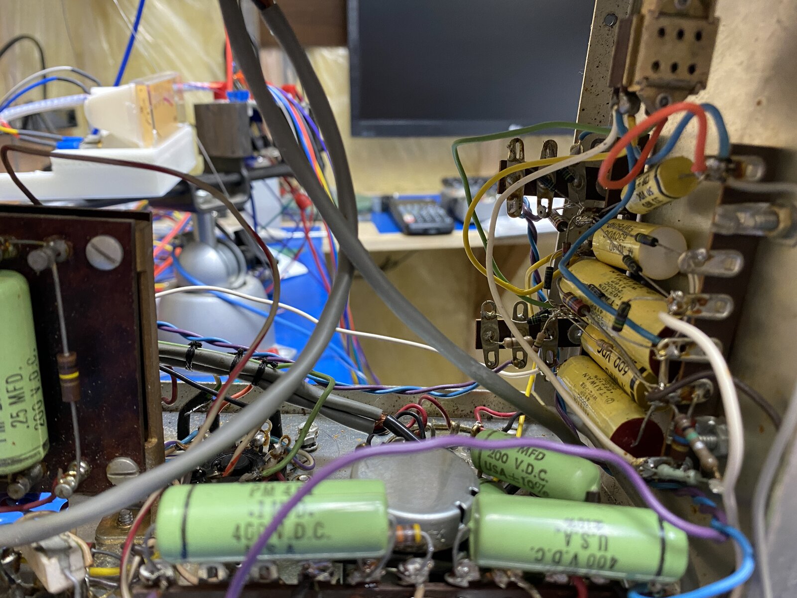
I'm not surprised it had a 5670 instead of the 6386, as 6386s te
I'm not surprised it had a 5670 instead of the 6386, as 6386s tested for matching halves have not been available for many years. The 5670 is about as close a replacement as can be found these days, but apparently does sound different at higher compression levels.
Here's an interesting piece on the Manley site about the 6386 availability problem, and the lengths that some will go to overcome it!
Looking back at my notes from perusing the schematic yesterday,
Looking back at my notes from perusing the schematic yesterday, I had jotted down a further couple of minor points that I'll mention here for completeness.
1) Bypassing the input pentodes changes the overall signal polarity from inverting to non-inverting, so either the wiring on the input or the output transformer will need to be changed to correct the input-output polarity. It's probably part of the JLM mods anyway.
2) The resistance values are strange in the R14, R15 meter adjustment. The other circuit half has 240R as the cathode resistor, but the meter feed section has 300R paralleled with 1K2 to 2K2 plus the meter resistance. This can only get down to 240R (to match the other half) when the pot is shorted out and if the meter has zero resistance. I would have thought that resistive balance at the 6386 cathodes was critical, as it determines the transconductance matching of the two sections. Prior to this schematic, I had not before seen the self-bias voltage of a valve being used to set the 0dB compression level on the meter. I think you should squeeze in a FET to buffer the cathode voltage to the meter and then change the cathode resistor to match the other half. Not.
Boswell, post: 467104, member: 29034 wrote: I'm not surprised i
Boswell, post: 467104, member: 29034 wrote:
I'm not surprised it had a 5670 instead of the 6386, as 6386s tested for matching halves have not been available for many years. The 5670 is about as close a replacement as can be found these days, but apparently does sound different at higher compression levels.Here's an interesting piece on the Manley site about the 6386 availability problem, and the lengths that some will go to overcome it!
I managed to get 6386 with no issue,maybe the supply chain is better now.
1) Bypassing the input pentodes changes the overall signal polarity from inverting to non-inverting, so either the wiring on the input or the output transformer will need to be changed to correct the input-output polarity. It's probably part of the JLM mods anyway.
I don't where the polarity was swapped on the JLM mod schematic, but it could be easily done via the J2 adapter.
2) The resistance values are strange in the R14, R15 meter adjustment. The other circuit half has 240R as the cathode resistor, but the meter feed section has 300R paralleled with 1K2 to 2K2 plus the meter resistance. This can only get down to 240R (to match the other half) when the pot is shorted out and if the meter has zero resistance. I would have thought that resistive balance at the 6386 cathodes was critical, as it determines the transconductance matching of the two sections. Prior to this schematic, I had not before seen the self-bias voltage of a valve being used to set the 0dB compression level on the meter. I think you should squeeze in a FET to buffer the cathode voltage to the meter and then change the cathode resistor to match the other half. Not.
That's a good thought, I am sure I can figure out a way to buffer the meter impedance from the cathode voltage.... Thanks for that!
I had a good look at the input transformer last night, mainly be
I had a good look at the input transformer last night, mainly because I got confused ;)
The Freed 34776 input transformer has 4 isolated windings according to the schematic. The wiring looks correct for pins 1,3,4,6,7 and 10.
Checking with ohmmeter I confirmed connectivity between pins 1 and 3 and pins 4 and 6. I had trouble measuring the secondary coils.
Then I noticed something odd, pins 8 and 9 are not, and have never been connected?
Bad picture but.... no solder on pins 8 and 9 ....
I checked for conductivity between pins 8 and 9 and confirmed there was none? Did this thing ever work? What am I missing?
Attached files 


Odd, indeed. All I can think of is that the model of transformer
Odd, indeed. All I can think of is that the model of transformer used does not have a CT secondary, and the circuit is relying on the junction of the two 30K pots (strange value!) to form a common-mode ground point in the original. If that's the case, then the mod of lifting the ground connection and applying the control voltage to this point will work just as well. I know there were many different versions of this box over its production lifetime.
I see you got a reply from Joe himself on the JLM forums!
Confirmed the secondary is a straight through coil, no center ta
Confirmed the secondary is a straight through coil, no center tap.
I started the mods last night. This box has clearly seen a few repairs and mods along the way. I almost feel like completely rewiring it.
I am very slowly working my way from the input the output investigating all of the changes made, this will take time.
With JLM mod the original input threshold circuit is bypassed. I have managed to remove it in one chunk, it can easily be put back in needed. But for now it is out the way.
I started to recap the main boards.
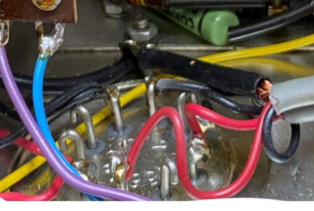
and I found this....the main power supply dropping resistor caught on fire at some point... its funny to me that someone used the burnt hole to feed wire through...
Good to see that somebody upgraded the resistor to a higher wattage ...
Attached files 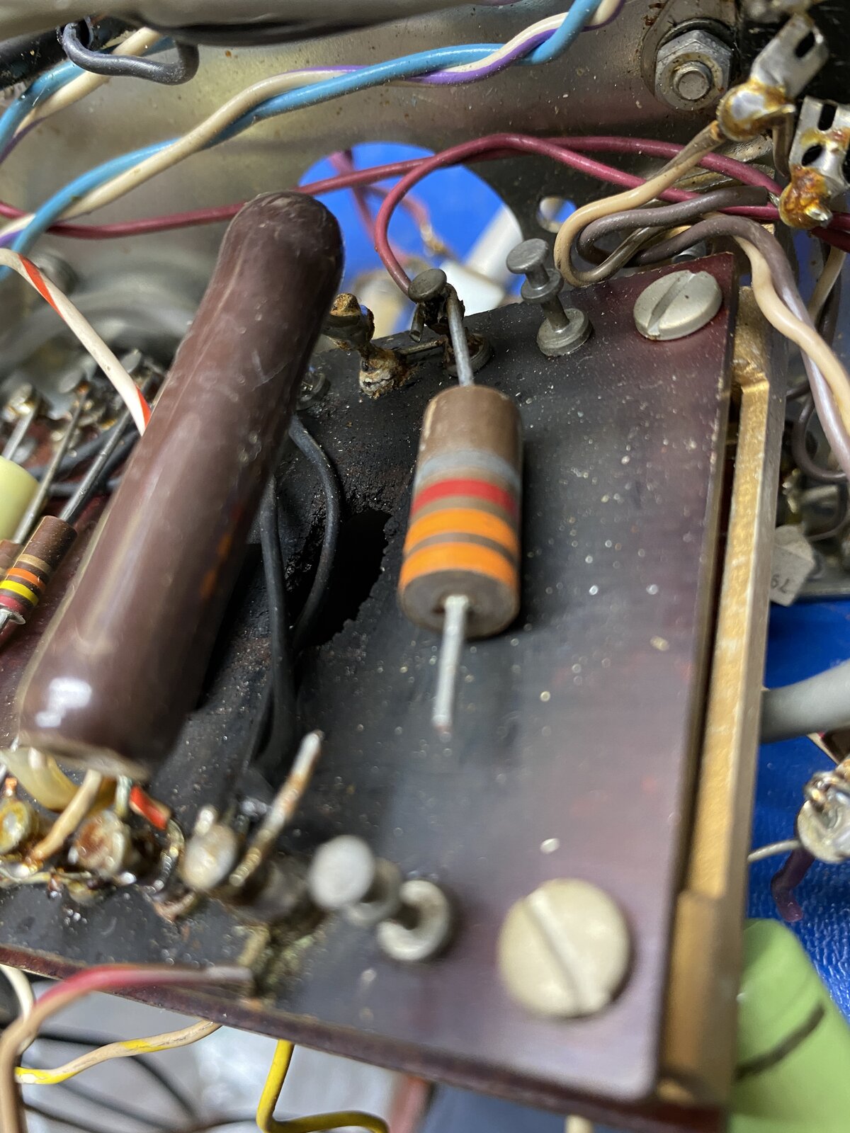
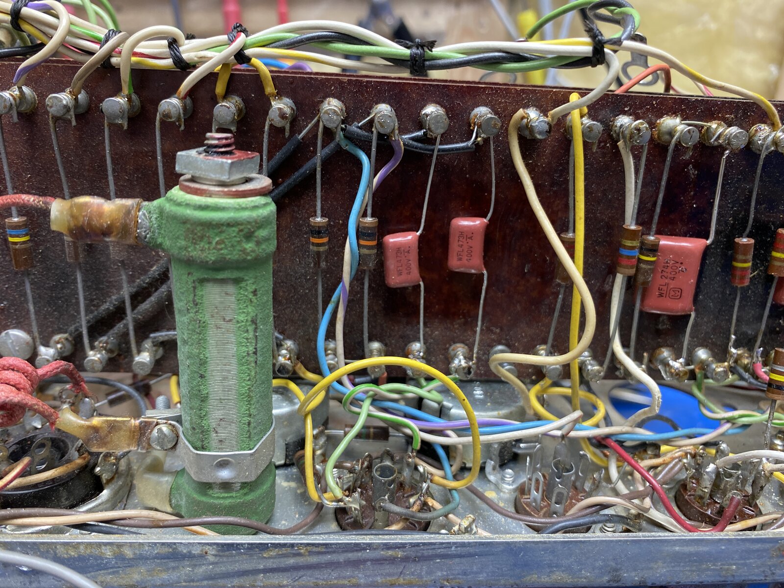
I have preformed most of the JLM mods now. The caps are done, a
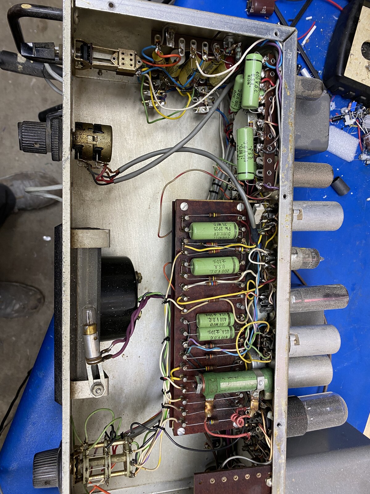
I have preformed most of the JLM mods now. The caps are done, a much of the failing wiring has been replaced. I have removed all not needed parts and the found mods in the hope to simplify future maintenance. The unit was a bit of mess. Lots of clean up and double checking to do before I retube and test the unit... but progress non the less.
Attached files 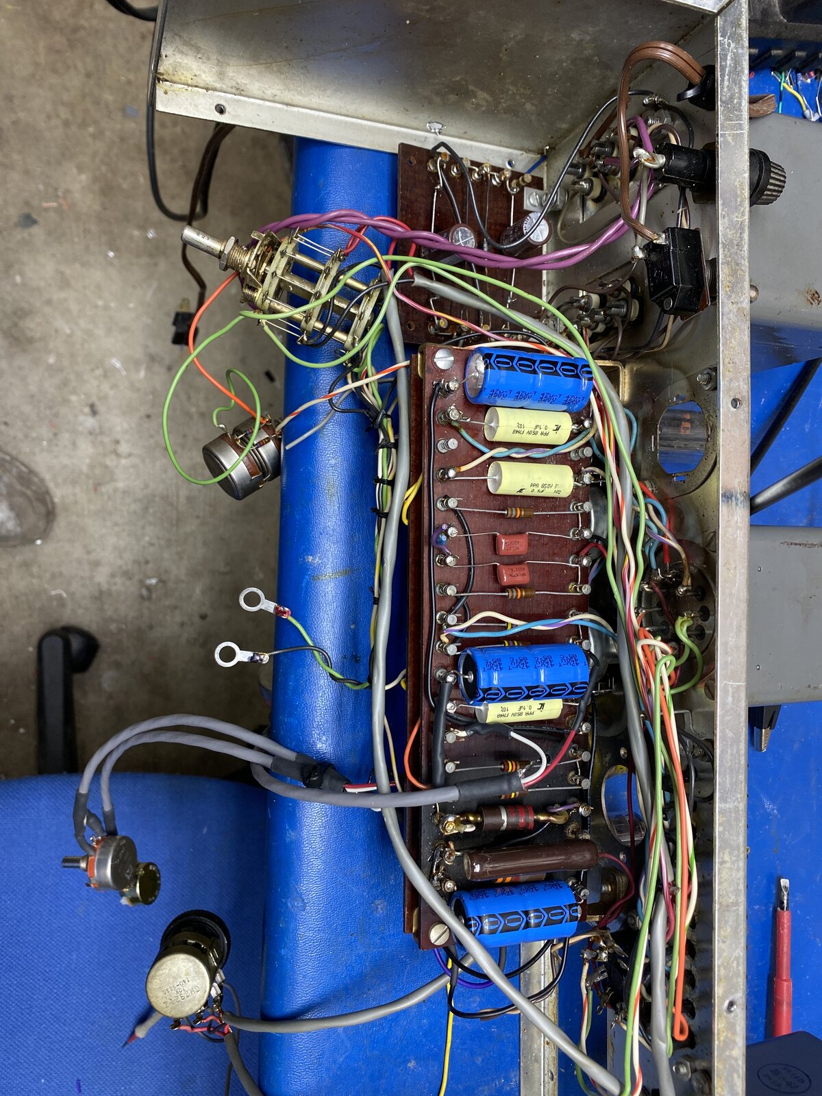


Boswell, post: 467184, member: 29034 wrote: You are obviously m
Boswell, post: 467184, member: 29034 wrote:
You are obviously managing to keep a clear head about what has to go where!
Lots of Pictures and notes. I have walked through every point of the circuit about 4 times now, there was so much "extra" in this box it was bit crazy. It will be a very simple circuit in the end. I am re-drawing the schematic to give to the owner for future work. This has definitely become a labour of love.
ok here is the redrawn schematic of what I have after the JLM mo
ok here is the redrawn schematic of what I have after the JLM mods. I am planning to add a FET buffer for the meter circuit and change R16 to 240 ohms, as Boswell suggested. But I haven't drawn that bit yet. I plan on using the the unused -18VDC supply for this.
This mod removes the V1 and V2 and all associated components. It also removes the J-1 Memory unit Plug and J-2 Stereo Expander plug. The owner has one unit and no plans to find and buy a second unit.
I added TRS input and output jacks as that is what the owner prefers to use. I tried to clean up the crazy metering wiring as best I could....
Attached files 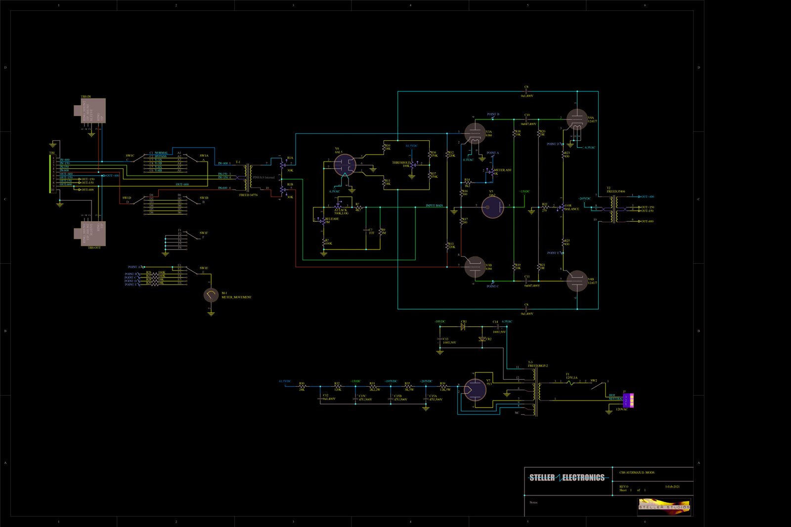
I have now walked through the circuit 3 times. I am ready to st
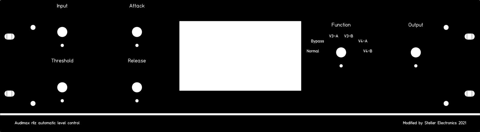
I have now walked through the circuit 3 times. I am ready to start testing! After discussions with the Owner it looks like I am making a new face plate for the unit. unfortunately the original faceplate not only suffered the years of use it also had several unsightly holes drilled into for the previous modifications... so I hoping to test out a friends new panel CNC with this:
Attached files 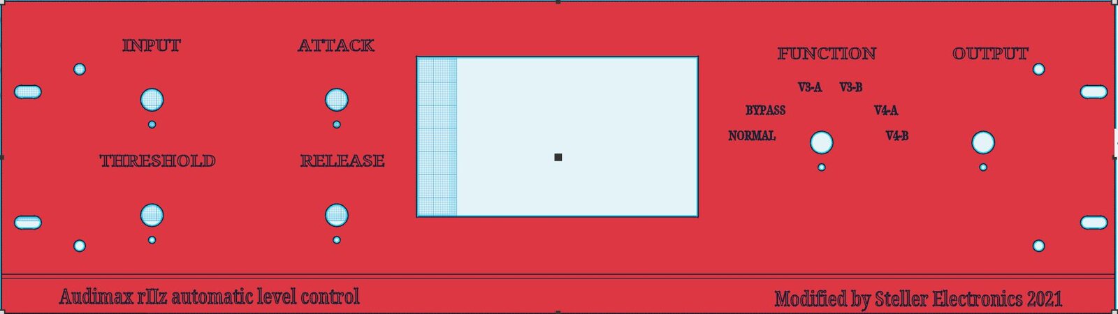

Link555, post: 467239, member: 31690 wrote: I have now walked t
Link555, post: 467239, member: 31690 wrote:
I have now walked through the circuit 3 times. I am ready to start testing! After discussions with the Owner it looks like I am making a new face plate for the unit. unfortunately the original faceplate not only suffered the years of use it also had several unsightly holes drilled into for the previous modifications... so I hoping to test out a friends new panel CNC with this:
Very nice, it would only be done in black with white engraving..
Professional job, Link! Did you have any more thoughts on buffe
Professional job, Link!
Did you have any more thoughts on buffering the meter drive? It's not completely straightforward if you want to avoid a junction voltage drop (transistor or FET). Simply using a FET-follower and adjusting the current so it's correct at 0dB will result in an error at other levels.
However, I'm not convinced that the original circuit would give correct readings for lower indicated levels, as there was no compensation for the standing current through the vari-mu triode. Maybe the printed meter scale allowed for this, but I have my doubts about that. Did you carry out a meter check with different level inputs?
There's also a problem with the way the original Function switch is configured. When switched to any of the positions other than Normal (GR), the loading on the cathode changes, resulting in the balance of the dual-triode currents being upset. Buffering the cathode feed to the meter and making the two cathode resistors the same value will correct that.
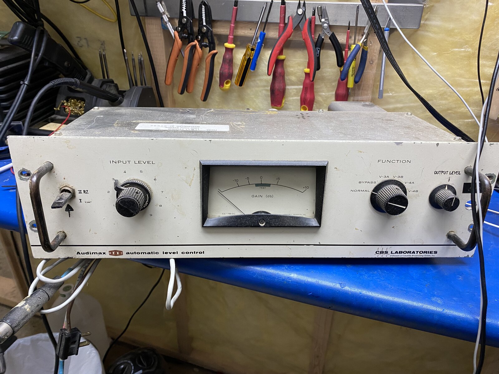
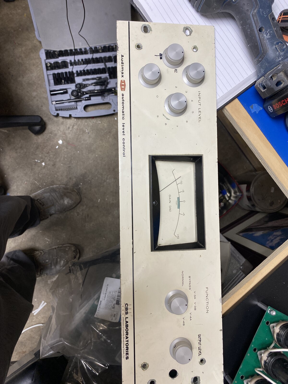
I've been meaning to ask: what is the switch with the platypus beak lever that has been added on the LH side of the old front panel?
Boswell, post: 467291, member: 29034 wrote: Did you have any mo
Boswell, post: 467291, member: 29034 wrote:
Did you have any more thoughts on buffering the meter drive? It's not completely straightforward if you want to avoid a junction voltage drop (transistor or FET). Simply using a FET-follower and adjusting the current so it's correct at 0dB will result in an error at other levels.
Not really ....I have been thinking about using the now unused -18vdc rail to power and some form of a wilson current mirror to drive the meter, but have not built anything yet. I made enough changes to debug for now , i was planning on getting the circuit stable then attacking the meter.
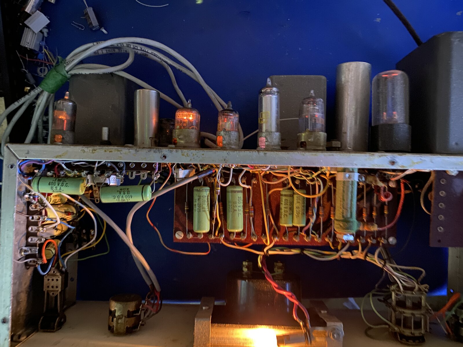
I fired it up last night with the mods and new caps and old tubes. I had enough time to check the voltages, all appears to be in the right ball park. It passed a sine wave, which it did not do previously. There is a problem with a dirty input pot, but otherwise it seems to have life even with old tubes.
However, I'm not convinced that the original circuit would give correct readings for lower indicated levels, as there was no compensation for the standing current through the vari-mu triode. Maybe the printed meter scale allowed for this, but I have my doubts about that. Did you carry out a meter check with different level inputs?
Not yet, the circuit was too noisy and Unstable before. Should be able to get some time for testing today.
There's also a problem with the way the original Function switch is configured. When switched to any of the positions other than Normal (GR), the loading on the cathode changes, resulting in the balance of the dual-triode currents being upset. Buffering the cathode feed to the meter and making the two cathode resistors the same value will correct that.
pretty sure the user will only ever use normal and bypass...can not see much value in checking v3 and v4 For him. But regardless, your right I will need at address the meter circuit.
Boswell, post: 467291, member: 29034 wrote:
I've been meaning to ask: what is the switch with the platypus beak lever that has been added on the LH side of the old front panel?
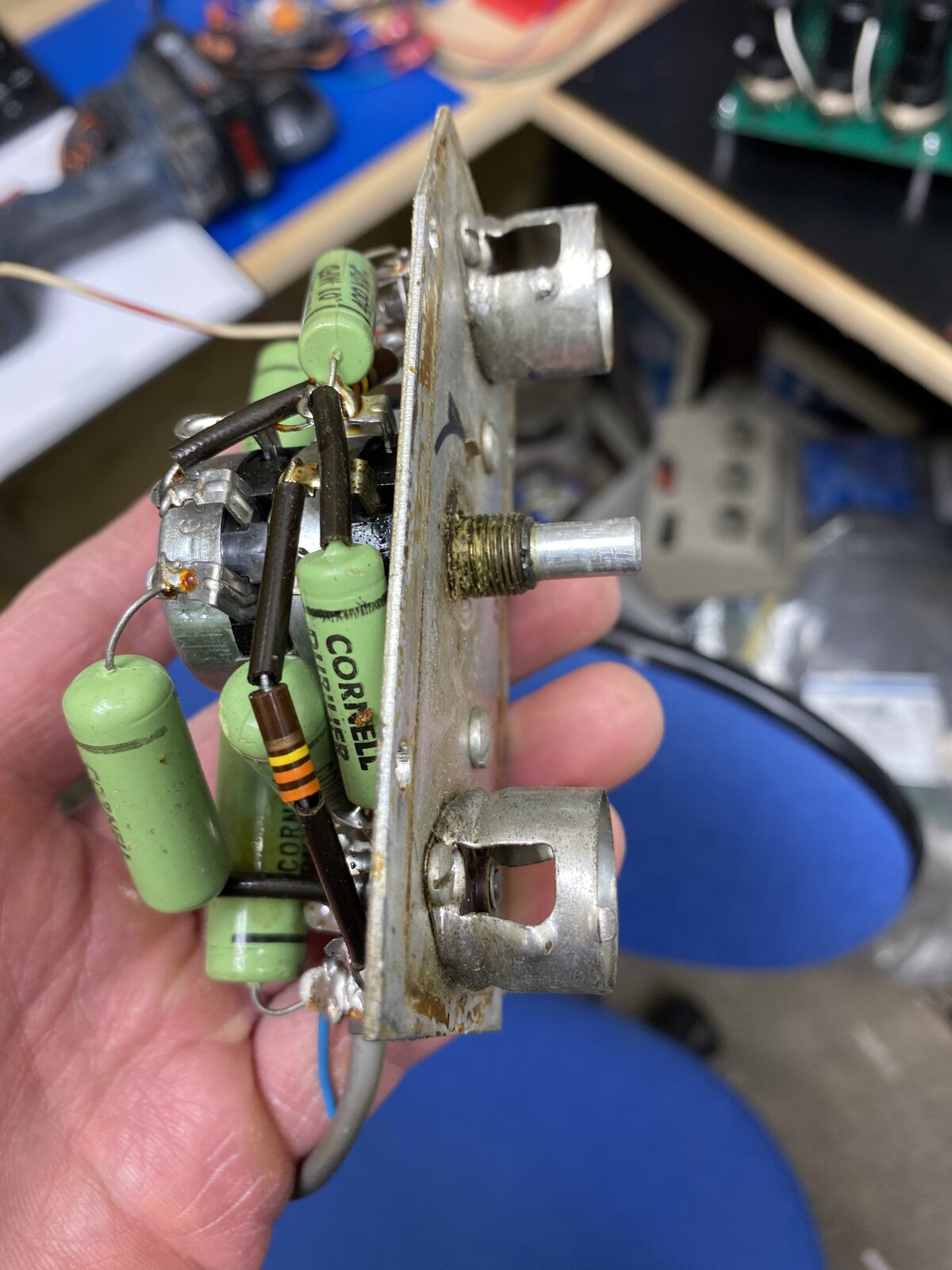
It appears to have been a filter selector, the previous mod removed the memory module and replaced it with a switchable rc filter. From the values it look liked in the first position it had a slow attack of ~10ms and release of 2secs, and in the second position it had nice attack of 20ms and release of 4 seconds....not sure how well it worked.

Link555, post: 467292, member: 31690 wrote: Not really ....I ha
Link555, post: 467292, member: 31690 wrote:
Not really ....I have been thinking about using the now unused -18vdc rail to power and some form of a wilson current mirror to drive the meter, but have not built anything yet. I made enough changes to debug for now , i was planning on getting the circuit stable then attacking the meter.
A current mirror to isolate the meter was a possible solution I had come up with as well, but as an NPN CM sitting on ground. You would still have the diode drop, but it would be constant and would cause no change of balance in the triodes when the Function switch was rotated.
Having the CM emitters at -18V and resistor-fed from the cathode would make the diode drop a negligible effect, but does not really give enough current variation over the range of compression, as too much of the current would be due to the 18V drop. It may be possible to use a zener in the emitter lead to get an intermediate voltage, so it would become a matter of balancing the error due to the diode drop against the range of current achievable. Sitting the CM on the -18 rail with a zener in the resistor feed to it from the cathode is an alternative. It would be simple with an op amp!
I think the thing to do is get the box working again and then measure the actual change in cathode volts over the working range of compression. We can re-visit the best way of doing the meter drive once the range figures are available.

Link555, post: 467045, member: 31690 wrote: In for a recap and
Link555, post: 467045, member: 31690 wrote:
In for a recap and retube and a few modifications. It’s missing the memory module....so it will need some thinking... Looks like a nice build so far..
Looks great Link
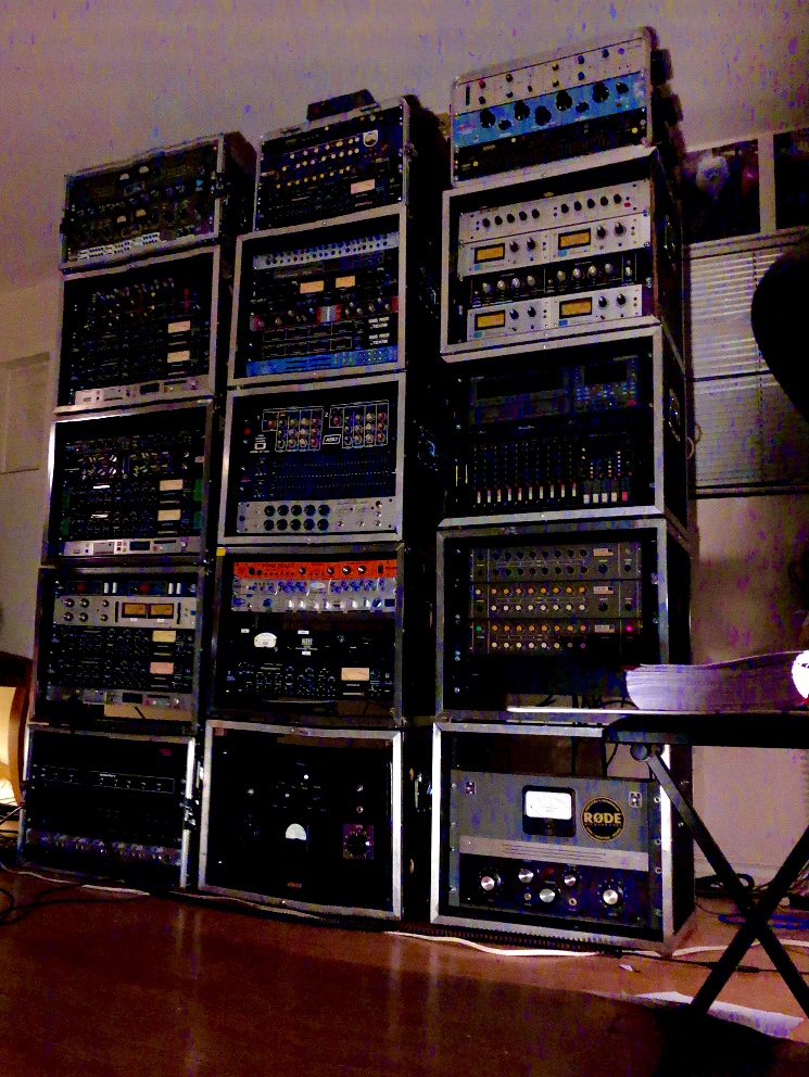
I’ll be adding another tower to the studio setup for it ... I’ve run out of rack space otherwise ;0)
Boswell, post: 467301, member: 29034 wrote: A current mirror to
Boswell, post: 467301, member: 29034 wrote:
A current mirror to isolate the meter was a possible solution I had come up with as well, but as an NPN CM sitting on ground. You would still have the diode drop, but it would be constant and would cause no change of balance in the triodes when the Function switch was rotated.Having the CM emitters at -18V and resistor-fed from the cathode would make the diode drop a negligible effect, but does not really give enough current variation over the range of compression, as too much of the current would be due to the 18V drop. It may be possible to use a zener in the emitter lead to get an intermediate voltage, so it would become a matter of balancing the error due to the diode drop against the range of current achievable. Sitting the CM on the -18 rail with a zener in the resistor feed to it from the cathode is an alternative. It would be simple with an op amp!
I think the thing to do is get the box working again and then measure the actual change in cathode volts over the working range of compression. We can re-visit the best way of doing the meter drive once the range figures are available.
That’s super helpful! and I agree get it working first then go back and play. Thanks yet again Boswell.
kmetal, post: 467295, member: 37533 wrote: Man, after these las
kmetal, post: 467295, member: 37533 wrote:
Man, after these last couple threads Link has made, it really made me realize how much consideration went into meters and metering. I really had no idea and took it for granted. Really eye opening stuff!!
Maybe I am just slow at it :
This post probably got lost in the server restart. As I s
This post probably got lost in the server restart. As I still had the email, I've re-posted it.
Link555 replied to a thread you are watching at Recording.org Community Forums. 07/02/2021, 17:19 (UK date and time)
After walking through the circuit again connections, I fired it up and confirmed it past audio. There was slight 120hz hum, but that was easily fixed by adding a proper ground connection to the input section. I changed the tubes one at a time. Changing the 6386 last removed all unwanted distortion, it now sounds pretty tight. I adjusted the output balance, the low end can really affected by this. i am not happy with the attack circuit yet, it seems to have little affect. I am going to focus on the threshold, attack and release to see if I can tweak the JLM values for this compressor. Also the output volume, was wired in a weird way that actually flips the polarity at low volumes...need to figure that out too...
Looks like not only is the memory module missing someone swapped
Looks like not only is the memory module missing someone swapped out the 6386 vari mu tube for a 5670... I am not sure that will work in a vari mu design. Also the input tube 6dk6 has been changed to a 6cb6a . suspect...