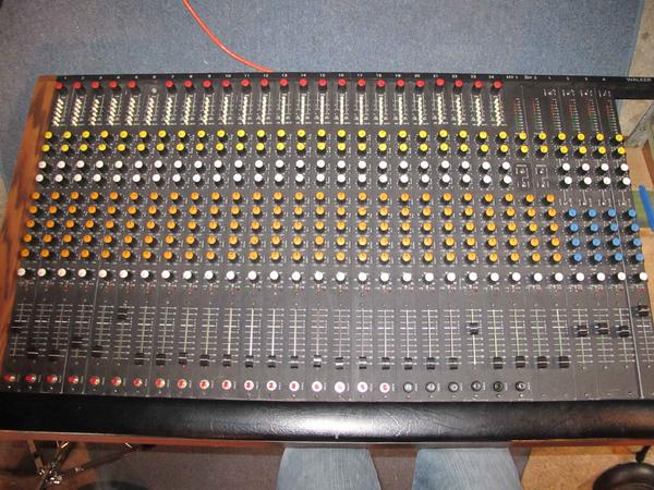
i had an 80's Walker Mixing Console givin to me without a power supply here are some photos - any leads/help?
Comments
The "P" could stand for "Phantom" power? Does the board have a +
The "P" could stand for "Phantom" power? Does the board have a +48V phantom power switch on each channel strip?
G=ground
+15VDC/-15VDC
P=+48VDC phantom power for condenser mics.
Unless you can find that particular brand somewhere, you would need to build one or buy one off the shelf.
You need one supply module +/-15VDC and that 3A figure might be the maximum current needed to power the board up at full load, so 3A output current.
If you can find a bench top linear power supplies that will give you dual channels for the +/-15VDC@3A, that would power up the mixing consoleand a good way to test the mixer out.
Those types of power supplies have short circuit proof features for testing stuff so it would be a good way to go.
You'll then need one supply module +48VDC with enough current to power 24 microphones.
The 48VDC Phantom power can be a separate supply (common the grounds of course) and I would think 0.5A-1.0A is enough current to power 24 mics simultaneously. If you need that. If your just using instruments and dynamic mics and don't care about using the phantom power then you can ignore that for now.
DIN connectors are pretty crappy poor connectors and easily fail to make connection very unreliable... so I have to agree with DVDHawk to replace it. I would just install a barrier terminal strip with screw terminals which will make it easy to hookup and test.
I'd start with just the +/-15VDC power supply first and test everything....
If you don't have the schematics you should try to find those....you might need it if it doesn't work.
You should be able to put a meter on that "P" lead (with no power hooked up) and press a phantom switch and see if you get some resistance reading or continuity....that would be one way to see if that "P" is the phantom power line.
Hope that helps
That would be what you need then. +/-15VDC supply and then a +48
That would be what you need then.
+/-15VDC supply and then a +48VDC Phantom power supply.
I would replace the DIN and still use a protected test power supply first and hook it up to +/-15VDC.
That way you can check the mixer. There could be some bad electrolytic caps in there so look at them and see if any of them show any leakage and look at the tops to see if any have any bulge.
You can always get a phantom power supply later if you need it.
The +/-15VDC supplies power to all of the circuitry for the mixer itself.
Also the same person who wrote 3A (black marker) on board also w
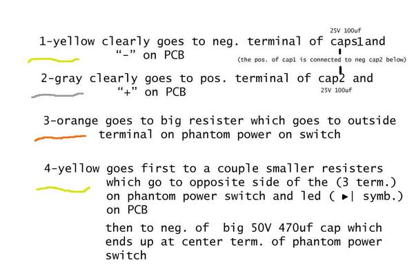
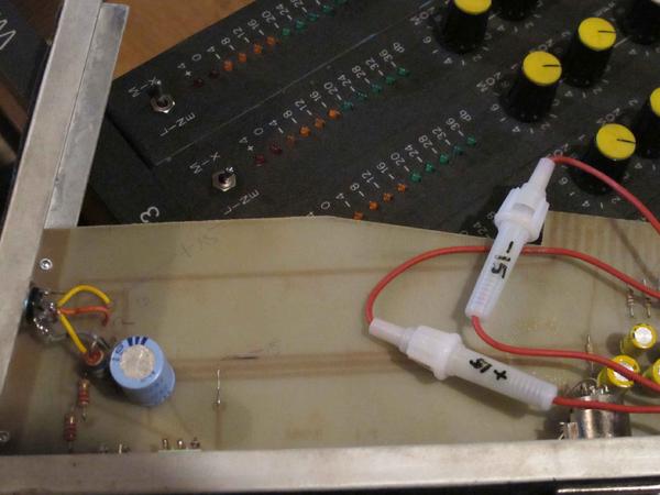
Also the same person who wrote 3A (black marker) on board also wrote "-15" on what looks like a fuse that comes from the 1-yellow line and respectively the other fuse labeled "+15" comes from the 2-gray line (both which correspond to a factory ,"-" and "+", label on board). this makes me think that these two lines are the -15V/+15V lines. unfortunately the guy who wrote in pencil/pen and probably installed the DIN had it wrong, and hopefully corrected it before attempting to turn on. (pencil/pen guy wrote -15 on 1-yellow, which seems right, but +15 on the 4-yellow wire?) - here's a pic of the fuses
Well the fuses will be the +15 and -15 power connections and tha
Well the fuses will be the +15 and -15 power connections and that's all you need to power up the mixer.
What value fuses are in there? That might help determine power requirements.
Is there any wattage listings anywhere on anything?
So did someone try to make a power supply for this mixer or is that the original board?
Are those automotive fuse holders something added by someone after the fact?
See this is why it would be handy to have schematics!
Your photos seem to only show small areas of the bigger picture.
It might be more helpful if you take a full photo.
your right those automotive looking fuses have been added after
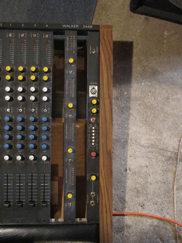
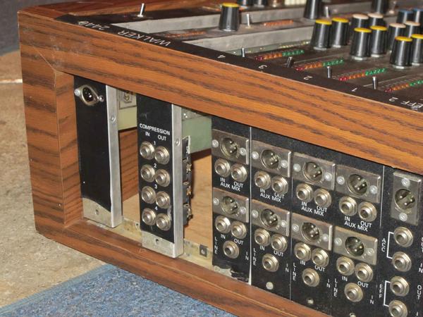
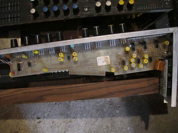
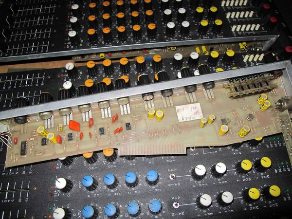
your right those automotive looking fuses have been added after the fact - they are F1.5A250V each. and clearly the guy who wrote "3A" on the board in marker installed these fuses. here are some more pics to show how i got it. the board is modular and i was told by the person i got this board from that the two spaces were blank strips which he has somewhere, it makes sense because the "ports" (where these modular strips fit into) aren't even screwed into the board where the blanks are - like all the other strips do. there are no wattage markings anywhere, everything here is original (except the DIN and the automotive fuses) the only time it says +/-15 is in marker on fuses and in pen by DIN wires, as i said they don't match. ARghhh.
I don't see an ON/OFF switch anywhere just the Phantom Power ON top right of mixer where DIN is on back, could the external power supply (that's missing) been the only ON/OFF switch?
So only label is Walker 2440? (which looks like a 24 channels/4
So only label is Walker 2440? (which looks like a 24 channels/4 bus 24X4).
Is there any other labels or markings on the mixer case on the back or on the boards inside?
You should take a close up of the channel boards showing the components and part numbers.
You could then find the datasheets and then verify the supply rail voltage for sure.
Someone must have figured out the +/-15VDC and that is the standard opamp supply.
1.5A per rail makes sense as that total of 3A would be the right rating for a dual output supply.
Maybe it never had phantom power if there are no individual switches to engage that per channel. Does it look like someone tried to add that to the mixer?
That would be sort of unusual having them either "all on" or "all off".
But like I said you don't need phantom power to test out the mixer.
Just use a dynamic mic or signal generator to test it with a dual output bench supply. If it all works great you could build a separate power supply box and replace the wire harness at the back or just continue to use the bench supply.
Looks like a project for sure...luckily it was free. It's 30 years old so who knows how much of it actually still works.
The only way your going to figure that out is to get ahold of a +/-15VDC bench supply and test it out.
A lot of those older mixers used external power supplies which were rack mounted or sat on the floor next to the mixer and that had the power switch on it to turn the mixer on. Then there was just a cable going to the mixer from the power supply box with the different voltages. There was always this idea that a separate power supply box located away from the mixer created less power supply hum and noise getting into the mixer itself. Many times the wire harness between the two was shielded to help keep any noise out as well.
So that's why the mixer itself doesn't have any power switch.
it definately has a factory phantom power on switch at the top r
it definately has a factory phantom power on switch at the top right of the board you can see it in the pic above, could it maybe have an auto detect/on when you plug in phantom powered mics? from what i've found already, Walker later Pulsar were made out of akron ohio in the late 70's into mid 80's and boards like this were sold to studios (no-one liked them for live because they weren't that sturdy construction-wise) in the 5-11 thousand range. no luck on schematics though. Wish i could borrow a PSU to try and see if she lights up, then buy if it does - would the 4-yellow (above chart) be the Ground?
just called the local electronics store and they say they have a
just called the local electronics store and they say they have a linear +/-15vdc power supply but he does know if its dual or not, and it doesn't have a ground, just two outs
-15vdc and +15vdc - no three prong plug - for $30! sounds cheap - maybe i could put a three prong on it then run that through to the ground (4-yellow) on the board?
You can use a meter and trace that out and verify it is the grou
You can use a meter and trace that out and verify it is the ground rail. Sometimes drawing out a schematic will help you see whats going on too.
That yellow wire was labeled G in the photo which would be ground and you said it goes to the negative side of the big cap...so that would be a good guess.
Here's a typical mic preamp circuit with +48V phantom power being switched in or out to a specific preamp channel.
http://www.thatcorp.com/datashts/dn140.pdf
That was the usual way to provide phantom power to a condenser mic plugged into the preamp.
This circuit uses +/-18VDC to power the preamp (V+/V-) but 15VDC was just as typical for supply rails.
Like I said the phantom power isn't important at this point.
Just find a +/-15V dual output power supply and see if the mixer and preamps work.
You can always buy a separate phantom power pak that connects directly to a condenser mic if that's what your using.
Any dynamic mic like a SM57/58 will work just fine without the need for the 48V.
stustustudio, post: 389006 wrote: just called the local electron
stustustudio, post: 389006 wrote: just called the local electronics store and they say they have a linear +/-15vdc power supply but he does know if its dual or not, and it doesn't have a ground, just two outs
-15vdc and +15vdc - no three prong plug - for $30! sounds cheap - maybe i could put a three prong on it then run that through to the ground (4-yellow) on the board?
It needs to be able to provide +15 AND -15 at least 1A with a common ground.
A three prong plug if your talking about the AC cord going into the power supply has nothing to do with the DC output.
Here's a schematic of a dual polarity power supply like what you
Here's a schematic of a dual polarity power supply like what you need
[[url=http://[/URL]="http://www.aaroncak…"]Dual Polarity Power Supply[/]="http://www.aaroncak…"]Dual Polarity Power Supply[/]
Here's another one: http://orca.st.usm.edu/~jmneal/dual_psu/
Here's another one:
Power supplies for $30 doesn't sound like the type of low noise,
Power supplies for $30 doesn't sound like the type of low noise, highly regulated power supply you want for powering an audio mixer.
If you have electronics experience and understand power supplies....
Something like this is what you can buy off the shelf without building you own power supply from scratch or a kit.
http://www.power-one.com/sites/power-one.com/files/lin_6.pdf
But....you would need to wire in a 3 prong grounded 120VAC power cord and power switch to these modules and some sort of chassis or panel to mount it all to so it's safe and sane.
You need the model that has dual output +15, -15 with a center tap transformer ground capable of providing 3amps similar to those schematics.
You can find bench test power supplies on Ebay or Craigslist pretty cheap.
Make sure they are dual and work of course.
I'm sure if those mixers cost in the thousands new, the power supply for it was probably worth at least $300.
Hope that helps
they say they don't have anything like that in stock (which make
they say they don't have anything like that in stock (which makes sense i live in a small town in bc canada) but they can order stuff from
http://www.e-sonic.com or
http://www.digikey.ca
currently looking for something there -
This would be the closest and cheapest route. [[url=http://[/UR
This would be the closest and cheapest route.
[[url=http://[/URL]="http://www.digikey…"]HBB15-1.5-A+G SL Power Electronics Manufacture of Condor/Ault Brands | 271-2280-ND | DigiKey[/]="http://www.digikey…"]HBB15-1.5-A+G SL Power Electronics Manufacture of Condor/Ault Brands | 271-2280-ND | DigiKey[/]
Like I said, you will need an AC power cord and a lighted power switch.
I'm assuming you have some ability with electrical/electronics?....If not then you should have someone who does hook everything up for you.
Maybe after you test it all and get it working you can mount the power module in that open space of the mixer with the power cord coming out the back and put the lighted power switch on the front blank panel.
stustustudio, post: 389039 wrote: sounds good, still don't get h
stustustudio, post: 389039 wrote: sounds good, still don't get how this thing gets grounded, this PSU only has two outputs (-15vdc and +15vdc)
If you look at the schematics I posted of that differential dual power supply, you'll see a wire in the center of the secondary side of the power transformer providing "ground" to the balanced DC +/- output rails.
That is the "center tap" winding of the power transformer and 0VDC (zero volts) between the two voltage rails.
That is what will go to the "G" connection of your mixer. If you were to take a voltmeter and connect its negative lead to that ground (0VDC) and the red positive lead of the meter to each of the 15VDC you will read +15VDC on one post and -15VDC on the other. You need that center tap on the secondary side to give you a positive and negative voltage.
If there was only two posts without the center tap winding for 0VDC ground you would have only +15 OR -15 depending on which leads of the meter you used not both....which is what I think that $30 one was.
Circuit ground is merely a reference point....voltages can be "below" ground (negative) or "above" ground (positive).
Don't get confused with AC ground (3 prong AC plugs) with DC circuit grounds. The AC ground is "chassis" or "earth" ground and DC grounds are "circuit" grounds which is the power supply 0VDC reference. That has the schematic symbol of a triangle with the small lines.
Correct. That PSU will have output terminals labeled with +15VDC
Correct.
That PSU will have output terminals labeled with +15VDC, -15VDC and GND.
If you mount the PSU in the case of the mixer you should run a green ground wire from the frame of that PSU to the chassis ground of the mixer case for AC shock safety.
Use a power switch in series with the "hot" (black) lead of the AC power cord (see schematic) that is rated for 120VAC/and at least 3-5A rating...a lighted switch is optional but worth having so you know its on.
The AC cord you use should have a green ground wire that should also be connected to the frame of the PSU module for shock safety. Again see those shematics.
Good luck....if you need more info or help just ask! Please be careful and never wire any of this stuff plugged in especially with 120VAC involved. Make sure everything is insulated and not touching anything else and don't touch any of it when it is hot.
15VDC @1.5Amps hurts a lot but 120VAC at even a couple of milliamps can kill you!
BTW...you can order this stuff yourself online you know...Mouser and DigiKey are great for all these parts.
your awesome, no worries i have some knowledge/experience. the
your awesome, no worries i have some knowledge/experience. the chassis of the mixer is all wood, and PCB - the only thing metal in there is the module frames/strips and a reverb tank. i'll take another look though - guess i'll just order it myself from digikey. (likely cheaper then local outlet)
I haven't checked back in the thread, but I was under the impres
I haven't checked back in the thread, but I was under the impression you needed +/-15V at 3A. Here are some of the linear regulated supplies that meet that spec from DigiKey CA:
[="http://www.digikey.ca/product-detail/en/HCC15-3-A%2BG/271-2285-ND/1035143"]HCC15-3-A+G SL Power Electronics Manufacture of Condor/Ault Brands | 271-2285-ND | DigiKey[/]="http://www.digikey…"]HCC15-3-A+G SL Power Electronics Manufacture of Condor/Ault Brands | 271-2285-ND | DigiKey[/]
[[url=http://="http://www.digikey…"]HCC15-3-AG Power-One | 179-2328-ND | DigiKey[/]="http://www.digikey…"]HCC15-3-AG Power-One | 179-2328-ND | DigiKey[/]
[="http://www.digikey.ca/product-detail/en/HCC15-3-A/179-2073-ND/146369"]HCC15-3-A Power-One | 179-2073-ND | DigiKey[/]="http://www.digikey…"]HCC15-3-A Power-One | 179-2073-ND | DigiKey[/]
[[url=http://="http://www.digikey…"]ACV15D3.0 Emerson Network Power | ACV15D3.0-ND | DigiKey[/]="http://www.digikey…"]ACV15D3.0 Emerson Network Power | ACV15D3.0-ND | DigiKey[/]
[="http://www.digikey.ca/product-detail/en/HCC15-3-A%2B/271-2032-ND/281725"]HCC15-3-A+ SL Power Electronics Manufacture of Condor/Ault Brands | 271-2032-ND | DigiKey[/]="http://www.digikey…"]HCC15-3-A+ SL Power Electronics Manufacture of Condor/Ault Brands | 271-2032-ND | DigiKey[/]
[[url=http://="http://www.digikey…"]HCC15-3-A+ SL Power Electronics Manufacture of Condor/Ault Brands | 271-2032-ND | DigiKey[/]="http://www.digikey…"]HCC15-3-A+ SL Power Electronics Manufacture of Condor/Ault Brands | 271-2032-ND | DigiKey[/]
These are all open-frame units, so you would need to house them for protection.
i guess the difference between the PSU suggestions is one is -+1
i guess the difference between the PSU suggestions is one is -+15vdc@3A- 45W or -+15vdc@3A- 90W , what would be more appropriate for this console?
Without having more accurate technical info on the power require
Without having more accurate technical info on the power requirements, you only have those fuses and the pencil markings to go on.
Getting the 3A unit would probably ensure you have enough power available and wouldn't hurt anything.
The 1.5A supply might be just fine but it might could be too small when all 24 channels and features are being used and things will start to "dim". It's hard to say with what you have. Both of those numbers could be wrong...you don't have enough info.
Again that's one of the reasons I suggested using a test bench power supply first so you can check stuff like that.
They have volt meters and amp meters on them to tell you how much current the unit is drawing when fully loaded.
If you could figure out what one channel card draws by looking at the number of opamps and components (again a picture of one of those would be helpful with the P/N's) you could roughly calculate the requirement per card and then multiply that number by 24 plus add a little extra and come up with a rough estimate.
That would get you closer.
Take a close up picture of one of the cards (full shot component side) and maybe we can figure it out.
Could you post the P/N's of the IC's and transistors from each b
Could you post the P/N's of the IC's and transistors from each board. Or take a closeup of them
Don't need the resistors or caps.
Can't read the numbers in the pictures.
Also if there are other boards with IC's and transistors that we can add into the load calc list those.
ARRGGHH try that again- Channel ------ 1 x M8128 LM339N --- 4
ARRGGHH try that again-
Channel ------ 1 x M8128 LM339N --- 4 x 115P LF 353N ---1 x P123 LF 353N --- 1 x 050 LM 394 CH
----------------------------------------------------------------------------------------------------------------
Bus ---------- 4 x CA 339 E RCA 006 --- 4 x 8045 LF 353N --- 1 x 8047 LF 353N --- 2 x NP2N 5210 EBC
stustustudio, post: 389096 wrote: ARRGGHH try that again- Chan
stustustudio, post: 389096 wrote: ARRGGHH try that again-
Channel ------ 1 x M8128 LM339N --- 4 x 115P LF 353N ---1 x P123 LF 353N --- 1 x 050 LM 394 CH
----------------------------------------------------------------------------------------------------------------
Bus ---------- 4 x CA 339 E RCA 006 --- 4 x 8045 LF 353N --- 1 x 8047 LF 353N --- 2 x NP2N 5210 EBC
Channel card:
LM339N = 2mA max
LF353N = 6.5mA max x 5 = 32.5mA
LM394N = 20mA max
54.5mA total x 24 = 1.308A
Bus card:
CA339E = 50nA x 4 = .2mA
LF353N = 6.5mA x 5 = 32.5mA
2N5210 =25mA x 2 = 50ma
82.7mA total
Total = 1.39A
So a really really rough guesstimate with 24 boards all powered and the bus board looks like 1.4 amps. So each 15V rail could easily need 1.5A.
Of course I could be completely off base here and still the 3A supply could be more correct.
The 3A certainly gives you some headroom on current capability. The 1.5A is right there at the max capability.
Maybe Boswell has an opinion on that and my calculations...
Is there anything else in the console to consider? You mentioned the compressor/reverb card?
Another method is to measure the resistance across each of the 15VDC rails to ground with cards installed. (No power applied). That resistance number can give you the equivalent circuit current needed at 15VDC. So you could do that calculation as well.
You could also look at the resistance value change as you plug in or remove a card and do the calculation for everything or just the load of one card or the bus card and so the math that way.
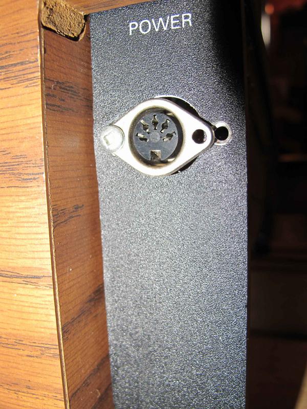
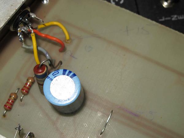


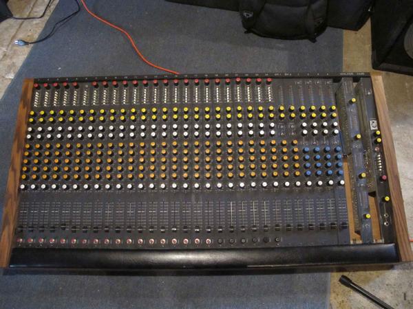

looks like there are 4 wires soldered to connector that have +15
looks like there are 4 wires soldered to connector that have +15V/-15V/G/P written in pencil beside them and there is a 3A written on the board