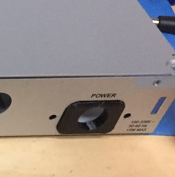
Currently working on replacing the flyback switching power supply in the Alesis DEQ830, with a linear supply.
This is an attempt to reduce the noise on the analog section of the circuit. It seems the ADAT inputs work well, but the analog inputs have a high noise floor. Looking at the schematic it appears the switchmode power supply is outputs +15vDC and -15VDC directly to the rails of the TL084 opamps on the line inputs of the circuit. But the digital supply get a 7vDC rail from the switchmode power supply, that becomes +5VDC via linear regulator. I am not sure why exactly they choose to not further regulate the analog section rails?
The switching noise on the rails is significant. (0.984Vpp)
The plan to replace the flyback switching power supply with a linear one and see if the rail noise is reduced.
I using a toroidal transformer that will outside of the DEQ chassis, and replacing the Flyback PCB with a new linear regulator PCB inside the chassis.
I got the 3D printer busy making a cable insert out of TPU to re-purpose the old 120VAC hole in the chassis.
Comments
Thanks Boswell! ... what your saying makes a lot of sense ...alt
Thanks Boswell! ... what your saying makes a lot of sense ...although I am not sure it is the case with this design that cable is about 10cm of 22awg , I see 7.1 volts on the output of the switcher, and 7.1 on the into to main boards linear regulators.
I completely agree that the coupled analog and digital commons is likely the cause of the noise, I am trying a linear supply to see if that can reduce the overall noise. I am sure there will still be some from the digital circuitry. It’s hard to tell which noise is worse , the digital circuit or the switcher power supply at the moment.
Mine is dead quiet. I bought it out of curiousity from a rental
Mine is dead quiet. I bought it out of curiousity from a rental company. It had never been rented out in it's first year. The internets told me it was a horrible EQ, even far worse than the DEQ230.
I'm strange. I do RTFM. And there it is, the way to go from balanced to unbalanced. If you miss that, it does sound bad.
If there's a design error, it's not having separate grounds for digital and analog. That could be better. But it doesn't result in "high" noise. Well, not higher than in most other budget gear.
Maybe the PSU in yours is defective?
After the new Power Supply was install the noise on the opamp ra
After the new Power Supply was install the noise on the opamp rails went from nearly 1Vpp to 0.07Vpp. Channel 1,2,5,6,7,8 all became deadly silent. 3&4 still made a hissing noise. After great deal of effort so disbelief. ...I traced it back to etching problem associated with the pcb around the channel 3 and 4 ADC (AL1101).
After careful inspection with a strong magnifier I found a hair off copper not etched near the ADC, I removed it with a small exacto blade, and the noise drop off significantly. This type of PCB problem is rare for a finished, inspected product. I guess the power supply noise was masking it during the QC?
yes sir U16, I actually swapped the Ch 1 &2 ADC with the ADC Ch
yes sir U16, I actually swapped the Ch 1 &2 ADC with the ADC Ch 3 & 4, thinking it was the ADC AL1101 chip. The hiss stayed on ch 3&4. I changed all of U16 resistors and caps , and the hiss remained, this convinced me it was the PCB. I reviewed the Alessis service manual and it looks this exact issue was not tested for in their test jig. I found it with headphones all all gains maxed. The biggest whisker was on the positive side 22uF electrolytic cap on the ADC side. There were several smaller ones around the VCC pin the AL1101. The etching process was light in the general U16 area.


Link555, post: 463870, member: 31690 wrote: Currently working on
This is standard practice for Alesis - the HD24 is a similar design, having an 8V feed, but the analogue rails are only +/-12V. The usual reason for local regulation (often called "point-of-load") is that the voltage drop in the cable appears on the input of the 5V regulator and not the output. Put the 5V regulator in the PSU and you get 4.5V at the target board if you are lucky, since you have to take into account the drop in the 0V digital return circuit as well. The analogue rails supply a much lower current load, so don't get the same treatment.
That said, what I do see from your photos is that there are only four power conductor leads coming from the supply to the PCB, so the digital and analogue circuits share a common ground, probably throughout the PCB. This may well account for a lot of the digital noise that is getting into the analogue signals.