Hi gang,
You know I own a few Focusrite ISA preamps. I'm considering buying a few attenuators to allow me to drive the transformer a bit harder and try to pull out a bit more mojo.
I currently record tracks with a peak range between -18db to -10db (on the preamp and on the DAW).
So my question is ; is it worth it ? Do pushing the transformer a bit more allow a more colored sound ?
About this item :
https://www.amazon.ca/dp/B0060GDZTG/?tag=r06fa-20
Topic Tags
Comments


Kurt Foster, post: 460592, member: 7836 wrote: why not just atte
Kurt Foster, post: 460592, member: 7836 wrote: why not just attenuate the DAW input?
Maybe we could be doing that - but we're talking more generally about attenuating the output of a transformer-coupled pre-amp before it feeds into an ADC.
The ADC could be part of an audio interface in front of a DAW, or it could be (as it often is in my live work) the the balanced insert returns of an Audient ASP880 that feeds via ADAT into an Alesis HD24XR hard disk recorder.

Kurt Foster, post: 460592, member: 7836 wrote: why not just atte
Kurt Foster, post: 460592, member: 7836 wrote: why not just attenuate the DAW input?
I will try it but if I push my ISA preamps, it might overdrive the ADC
In my case, I only have one setting for all the interface inputs (-10db +4db) and I'm using other preamps which would not be a good Idea to push that far...
I'm thinking of attenuating only 2 or 4 channels.
Boswell, post: 460588, member: 29034 wrote: I made a set of 12dB balanced attenuators for my API3124+ pre-amps, as the output transformers don't start to wail until you get to about +32dBu. This is too much for most recorders, ADCs or mixers that I might want to send them to.
Wow, that would be so nice of you. It would be nice to do them myself and save a few bucks.
Another question would be how much attenuation the ISA's would need ? 10 -20 db ?
pcrecord, post: 460594, member: 46460 wrote: Another question wo
pcrecord, post: 460594, member: 46460 wrote: Another question would be how much attenuation the ISA's would need ? 10 -20 db ?
I would look up the full-scale dBu value of all the inputs that you might want to feed from the ISA outputs and note the lowest. The only figure I can find for the ISA maximum output is +25dBu, which doesn't strike me as exceptionally high. I would be surprised if the lowest figure on your list of inputs was less than +20dBu, so something like 6dB attenuators could well cover all eventualities.
The 6dB figure is easy, as it's a 1:2:1 ratio of resistors in a U-shape on its side. So, as an example using 1% range resistors, 1K Ohm in series in the signal lines and 2K Ohm shunt across the driven input would give the correct ratios and a reasonable level of load impedance when plugged into line level inputs. If the line inputs are lower than about 10K Ohm input impedance, go up to a 2.2K Ohm shunt. The values are not critical, as long as all the attenuators use the same resistor values in the equivalent places.
I haven't recently been able to find for sale the unwired XLR barrel M-F adaptors designed for this type of thing. I bought some Canford ones many years ago, but I don't see them in their latest web catalogue. If you don't fancy stuffing resistors inside XLR connectors (the two series ones in the XLR-F and the shunt in the XLR-M), then you could get some short XLR patch cords, cut the signal conductors in the middle and insert the three resistors there, leaving the screen wire continuous to take the tensile forces.
Even if a 6db might be enough, I think I'd like to aim at 10 or
Even if a 6db might be enough, I think I'd like to aim at 10 or 12 db. I like my tracks to be recorded at -18db specially on projects with 30 and more tracks.
Will it be too much ? I'm such a newb in electronic circuit. Do you have a schematic or photos of the circuit I'd need to build.
There is a store in MTL that has a lot of components, I'll check if I can fin the XLR Barrel.
If i don't find XLR barrel, I will do it in boxe(s) with 2 or 4
If i don't find XLR barrel, I will do it in boxe(s) with 2 or 4 channels in the same box..
Chassis mount connectors aren't expensive !
Or if I find Xlr to TRS adapters big enough to be modified, it could also work since I'm going to TRS inputs anyway. I still have many TRS cables I used with the patch bay I don't use anymore...
;)
I would have thought that, seeing these attenuators would be use
I would have thought that, seeing these attenuators would be used on the output of the ISA pre-amps, the tracks will be incorporated in the mix at a level appropriate to the mix. The level at an input is normally set by the channel's 0dBFS at the top end and the channel's noise level at the lower end, allowing sufficient headroom (e.g. 20dB). Over-attenuating at an input has the effect of raising the noise floor on that track since you have to use more gain to bring it up to mix level. I've been taken to task in the past about this, as some people argue that it's noise-free digital gain on a 24-bit converted signal, completely missing the point that the converted signal includes a representation of the analogue noise floor at the channel's input.
I'm assuming that the -18dB you mention is an r.m.s. level and not a peak. If you are using your FF800 as an ADC, the line inputs of that unit have an 0dBFS of +19dBu (on the +4dBu setting), so -18dBu input is 37dB of headroom! I'm not being critical, Marco, it's just that I'm not a fan of relating the analogue level going into your DAW to the number of input tracks in a mix.
XLR or TRS connectors are fine for this high signal-level work. Building the attenuator in a box with 4 XLR(F) inputs and 4 TRS jack outputs would be good, and it would do your XLR-TRS conversion for you.
I'll put together a table of suitable resistor values for various different attenuations in the range 3dB - 20dB.
Here you are: Attached files In-line attenuator.pdf (2
Here you are:
Attached files In-line attenuator.pdf (21.5 KB)
While rummaging in my electronic archives for something else, I
While rummaging in my electronic archives for something else, I came across a photo of the innards of a small 12dB two-channel attenuator box I built in a hurry some years ago. This was for reducing the +32dBu output of my API3124+ pre-amps to +20dBu when I needed to feed the balanced ADC insert returns on my Audient ASP880 for recording purposes. The box also has switchable 0dB/12dB attenuation outputs for routing to a mixer for live use.
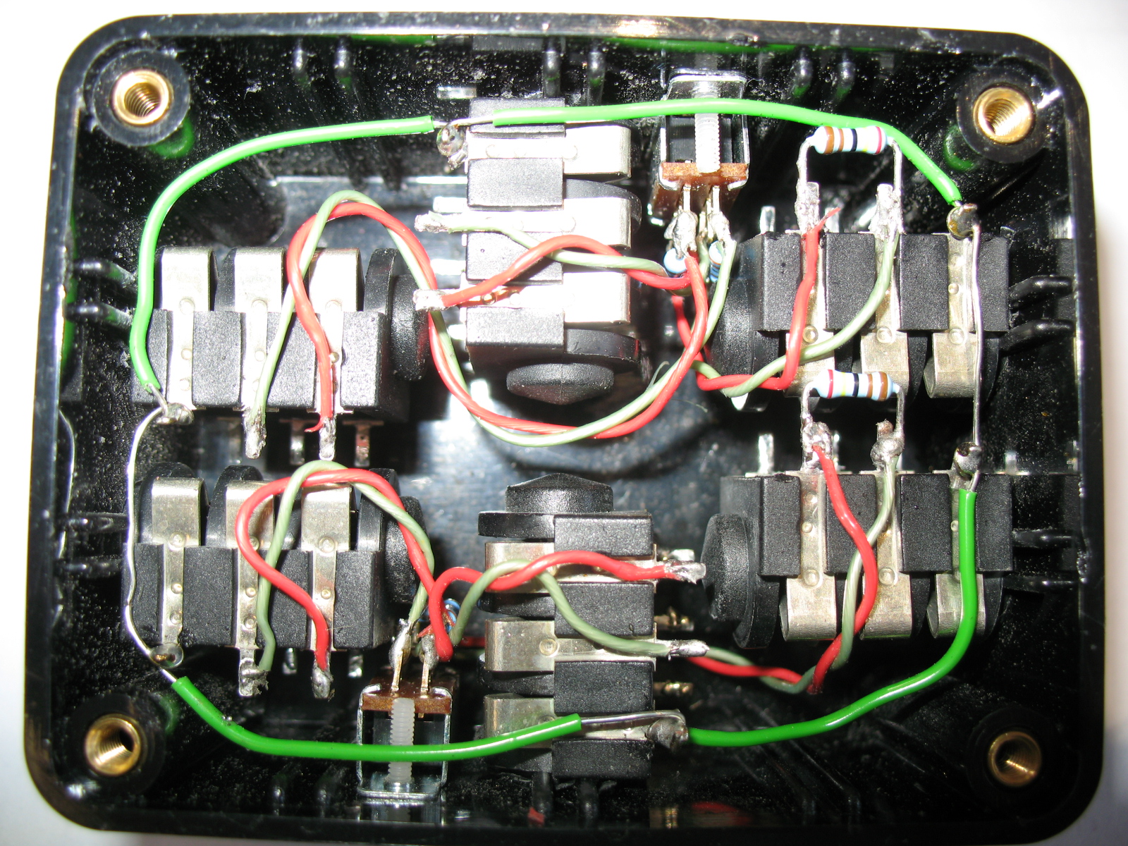
The inputs are on the left, the switchable outputs top and bottom, and the fixed -12dB outputs on the right. The switches are adjacent to their respective jacks. The series attenuation resistors are just visible mounted on the switch contacts, and the shunt resistors are across the signal terminals of the output jacks.
I see I chose standard metal film 1/4W resistors for the attenuator components, but they were probably what I had to hand at the time. In operation, the box deals well with +32dBu inputs.
pcrecord, post: 460634, member: 46460 wrote: WO ! this is some t
pcrecord, post: 460634, member: 46460 wrote: WO ! this is some tight space work !! ;)
I thought that getting the two input jacks and the two -12dB output jacks into that little box would be tight. Then I came up with the need for mixer output jacks as well, plus the level switches. I remember it took a bit of working out how to get it all in there to leave the unswitched jack connection tags accessible.
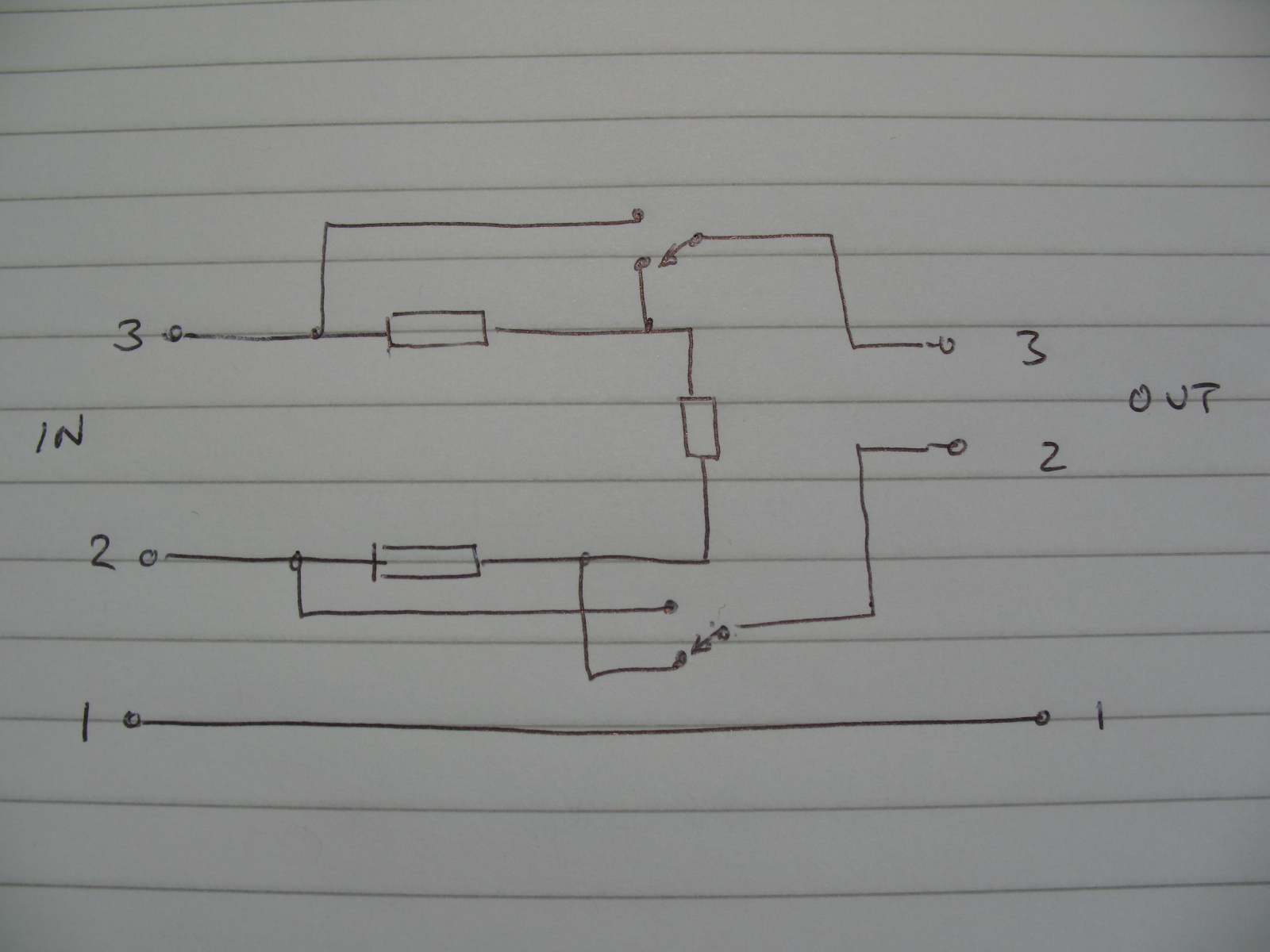
Hey Boswell, I received all my parts and I thought I'd add a byp
Hey Boswell, I received all my parts and I thought I'd add a bypass switch to the design.
I got those switches that seemed to be a good choice, 6 pins ON/ON 2 Position DPDT :
https://www.amazon.ca/gp/product/B01D1D0UAC/?tag=r06fa-20
Would this make sens ?
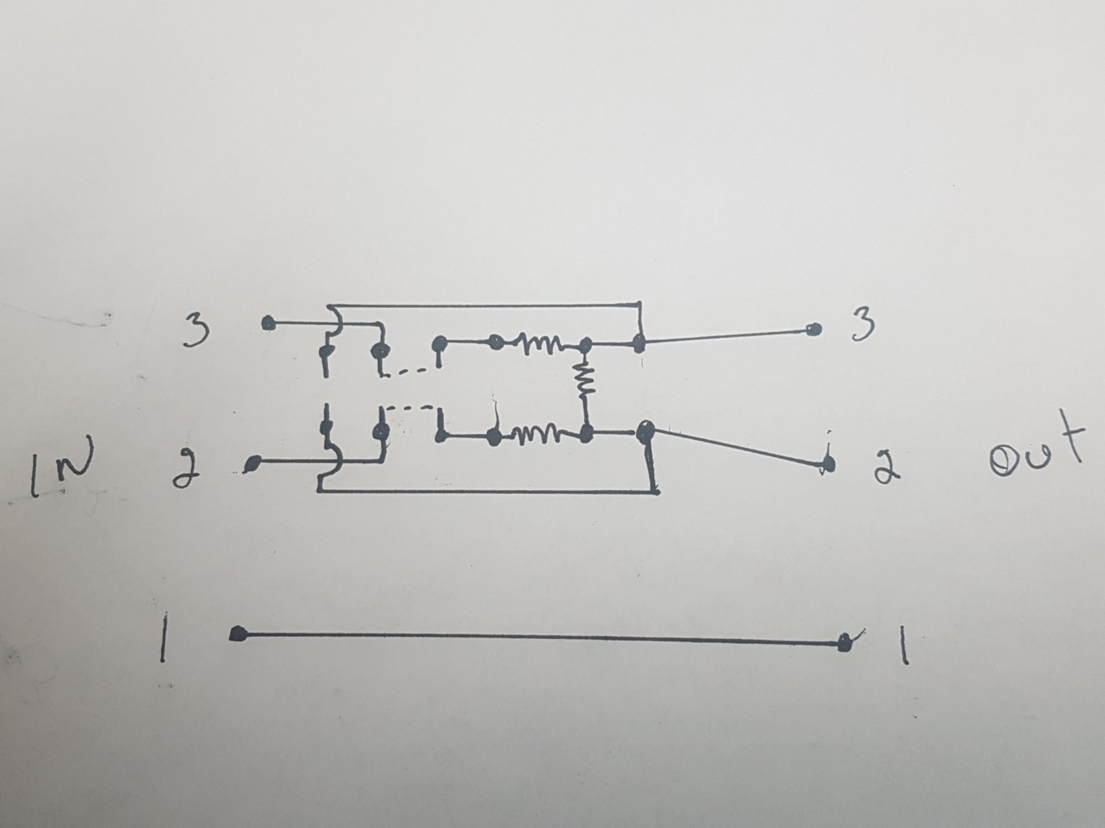
I took time to analyse your new design. So instead of being at
I took time to analyse your new design.
So instead of being at the output, the resistor will still be across the 2 and 3 pin but at the input and behind the 2 other resistors.
I get that the sum of all 3 resistors will be higher, but will it still affect the signal coming in ?
I'm planning the 10 db attenuation so 2.2k x 2 and 2k will be the values.
Great info... Since the Focusrite ISA impedance settings goes l
Great info...
Since the Focusrite ISA impedance settings goes like this : The low impedance setting is 600 ohms. The setting labeled ISA 110, which is modeled on another piece of equipment in the ISA range, is 1400 ohms. Medium impedance is 2400 ohms. High impedance is 6800 ohms.
So I should only avoid 600 ohms, I guess...


Nice work! I was grooving to the music in the background. Some
Nice work! I was grooving to the music in the background. Some circuits seem more complicated on paper than in actuality to my untrained eyes.
What do you think a circuit board would improve, and could heat shrink tubing be used instead of double sided tape? Also, how much more complex would it be to have used a variable, stepped gain knob, or rotary switch, instead of a toggle switch?
Looking forward to the sequel!
kmetal, post: 461033, member: 37533 wrote: Also, how much more c
kmetal, post: 461033, member: 37533 wrote: Also, how much more complex would it be to have used a variable, stepped gain knob, or rotary switch, instead of a toggle switch?
The essence of an attenuator box of this sort is that the attenuations are known and repeatable, both over time and over channels. Switches rather than infinitely variable controls are preferred for this.
Marco's box (and also the box that I posted a photo of) had two attenuation settings, so a simple DPDT toggle switch suffices. With some fudging, 3 settings would be possible using a centre-off toggle switch, but 4 or more postions requires a rotary switch. You need at least two resistors per additional setting, so the switch gets a bit bristly fairly quickly.
kmetal, post: 461033, member: 37533 wrote: Nice work! I was groo
kmetal, post: 461033, member: 37533 wrote: Nice work! I was grooving to the music in the background. Some circuits seem more complicated on paper than in actuality to my untrained eyes.
What do you think a circuit board would improve, and could heat shrink tubing be used instead of double sided tape? Also, how much more complex would it be to have used a variable, stepped gain knob, or rotary switch, instead of a toggle switch?
Looking forward to the sequel!
Having a circuit board would eliminate any short-circuit risk. Heat shrink is a good idea but the U shape of the resistors placement make it hard to well isolate it from the input connector.. I would need to put small shrink cable on every resistor seperatly.
Frankly, I was a bit too exited to finish it to wait an buy more parts..
I think Boswell should answer about using a stepped variable gain knob. Not sure how it would interact with the design.. EDIT : he just did in the previous post !
I have a few recording to do for customers.. but I'm also exited about the next step, listening to the difference.. ;)
My other (basic) question is how do you figure out which resisto
My other (basic) question is how do you figure out which resistor(s) are appropriate for a given gain reduction. How do you know what to use for say -10db like marco did vs -15, -20, -25db, ect, ect?
Also does it vary based on input? Like is box was receiving mic level, line, or a guitar?
Bos, is better placed to explain since he is the one who supplie
Bos, is better placed to explain since he is the one who supplied those numbers... but the values are based on line level and the values result of some basic calculations I didn't learn, yet...
I remember touching this at school 35 years ago and never thought that some day I could be interested in this :)
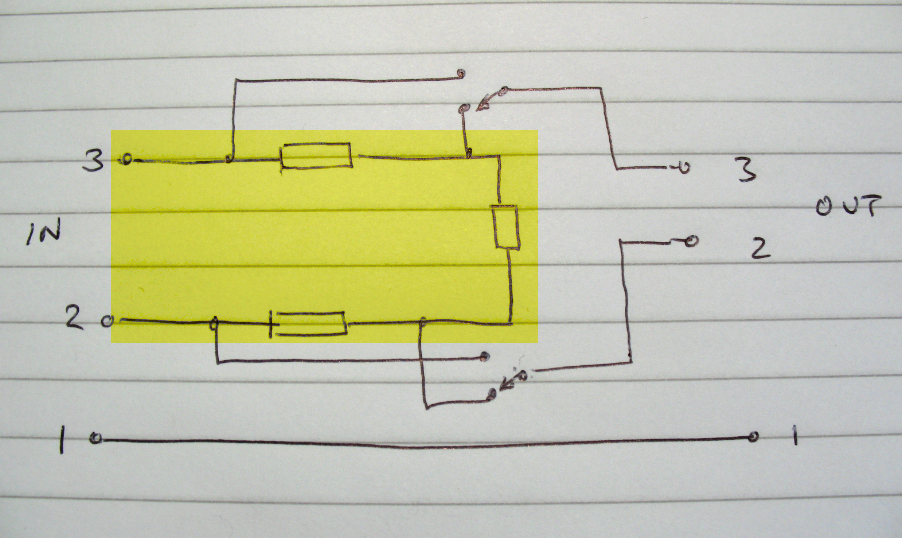
The table of resistor values I gave Marco were for a U-pad balan
The table of resistor values I gave Marco were for a U-pad balanced line-level attenuator. It's made up of three resistors: two identical values in series with the positive and negative input feeds respectively and a shunt resistor across the output. It's not difficult to calculate the ratio of shunt to series resistance needed for a given attenuation if you assume the source impedance is zero and the destination input impedance is infinite. Note that the circuit is symmetrical through the centre of the shunt resistor, with this centre point being at zero volts (a virtual ground). You simply calculate the values for either the upper section or the lower section, giving the series resistor and half the shunt resistor.
If the ratio of series to half the shunt is K, then the formula for an attenuation of dB is K = Alog(dB/20) -1, where the antilog is base 10. In practical terms, round the logs with care, e.g. take log(2) as 0.3 rather than 0.301023
As an example, for a 12dB pad, K = Alog(12/20) - 1 = Alog(0.6) - 1 ~= 4 - 1 = 3, so the series resistor is 3 times half the shunt, or 1.5 times the shunt value.
However, there are other factors to consider and adjustments to be made.
1. The reference resistance of (say) the shunt: e.g. Ohms, KOhms or MOhms?
2. Resistor noise if it's for low-level signals
3. Correcting for non-zero source impedance
4. Correcting for non-infinite load impedance
5. Mapping the corrected calculated values on to the standard set of available (preferred) values in the E24 or E48 ranges
6. Checking the power dissipation for high-level signals, including the change of resistance with temperature (from heating effects)
7. Checking the resistance-voltage characteristics of the chosen type of resistor (often overlooked, but usually unimportant for leaded parts)
8. Repeating all of the above when your supplier is out of stock of the values you have chosen
Ahh, the life of a design engineer...
Boswell, post: 461059, member: 29034 wrote: The table of resisto
Boswell, post: 461059, member: 29034 wrote: The table of resistor values I gave Marco were for a U-pad balanced line-level attenuator. It's made up of three resistors: two identical values in series with the positive and negative input feeds respectively and a shunt resistor across the output. It's not difficult to calculate the ratio of shunt to series resistance needed for a given attenuation if you assume the source impedance is zero and the destination input impedance is infinite. Note that the circuit is symmetrical through the centre of the shunt resistor, with this centre point being at zero volts (a virtual ground). You simply calculate the values for either the upper section or the lower section, giving the series resistor and half the shunt resistor.
If the ratio of series to half the shunt is K, then the formula for an attenuation of dB is K = Alog(dB/20) -1, where the antilog is base 10. In practical terms, round the logs with care, e.g. take log(2) as 0.3 rather than 0.301023
As an example, for a 12dB pad, K = Alog(12/20) - 1 = Alog(0.6) - 1 ~= 4 - 1 = 3, so the series resistor is 3 times half the shunt, or 1.5 times the shunt value.
However, there are other factors to consider and adjustments to be made.
1. The reference resistance of (say) the shunt: e.g. Ohms, KOhms or MOhms?
2. Resistor noise if it's for low-level signals
3. Correcting for non-zero source impedance
4. Correcting for non-infinite load impedance
5. Mapping the corrected calculated values on to the standard set of available (preferred) values in the E24 or E48 ranges
6. Checking the power dissipation for high-level signals, including the change of resistance with temperature (from heating effects)
7. Checking the resistance-voltage characteristics of the chosen type of resistor (often overlooked, but usually unimportant for leaded parts)
8. Repeating all of the above when your supplier is out of stock of the values you have chosenAhh, the life of a design engineer...
Awsome, thanks! Cant wait to give this a try.
Looks like a lot of work went into that video, Marco - well done
Looks like a lot of work went into that video, Marco - well done!
One thing you showed is that the ISA can deliver clean signal at more than 10dB greater than the FF800 will handle at its line input, which corresponds with the specifications of the two boxes. The ISA output levels before clipping are very difficult to find in the literature, and, as far as I can find, vary in the range +24 to +26dBu between the different ISA models.
If you want to find out what your ISA output clipping sounds like, you could connect those attenuators in series to get enough dB reduction so that the FF800 line input does not overload. Because of impedances, you won't get exact multiples of 10dB reduction, but that doesn't matter in this case.
That was a test I carried out when I first got my API 3124+ pre-amp some 12 years ago, with the effect I was looking for being output transformer saturation. In the Focusrite ISA range, the models vary as to whether they are a dual-transformer design or have only an input transformer, so you would have to check the architecture of your particular model.
Boswell, post: 461148, member: 29034 wrote: If you want to find
Boswell, post: 461148, member: 29034 wrote: If you want to find out what your ISA output clipping sounds like, you could connect those attenuators in series to get enough dB reduction so that the FF800 line input does not overload. Because of impedances, you won't get exact multiples of 10dB reduction, but that doesn't matter in this case.
I thought about this, I will certainly try it. If I finally get more mojo out of it, I'll do one more video about it...
What surprised me was that even with the clipping led on the ISA is still clean. It just reinforced my love for them ! ;)
Well done. I wish more pres came with an output attenuation knob
Well done. I wish more pres came with an output attenuation knob. That's one very useful thing Warm audio added to their api clone. With digital level to disk being somewhat standard, vs tape, the output knob is really crititcal imho.
Boz brings up interesing design differences among the ISA models.
I have to say this video and conversation has me leaning a bit more towards the RND 511 pre vs the ISA for my next pre.
The attenuation box seems like a very useful peice.
kmetal, post: 461153, member: 37533 wrote: I have to say this vi
kmetal, post: 461153, member: 37533 wrote: I have to say this video and conversation has me leaning a bit more towards the RND 511 pre vs the ISA for my next pre
The 511 seems a very good choice for someone already having a lunchbox. I don't think Focusrite offers the ISA in that format, but if you could find a used Red per.. this could be interesting too !
Very different beasts, the texture and silk option of the 511 seems to be appealling. I know you often aim for some mojo sounding gear.
I remember you telling me about the LA-610 and how you would push everything to maximum to see how it sounds.. eh eh eh ! ;)
I'm changing the tubes on one of them in a few weeks, I'll probably do a video on it too.. Stay tuned for that !
But this experience with the attenuator re-confirmed to me that the ISA is all about Clean sound, no noise, no distortion.. but still offers this nice transformer sound.
Yes, attenuators on the output of pre-amps do allow you to push
Yes, attenuators on the output of pre-amps do allow you to push them a bit harder. I made a set of 12dB balanced attenuators for my API3124+ pre-amps, as the output transformers don't start to wail until you get to about +32dBu. This is too much for most recorders, ADCs or mixers that I might want to send them to.
Balanced attenuators are easy enough to to make yourself if you are handy with a soldering iron. I can give you the formulae for resistor values. The advantage of making them yourself is that you can choose exactly the type of resistors that are going into them, and therefore know that they will not wilt or change their value appreciably at these high levels.