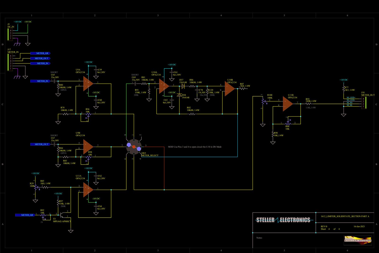
So I was so interested in the 1612 Tubes I got to play with... I started a hybrid design. The concept is a vari-mu style compressor using the 1612 as the front end after a Jensen XFMR. I am thinking of then running LA2 style buffer and driver amplifier into a Jensen output XFMR. But the side chain will be solid state and use either a LOG amp or a THAT audio engine.. Sort of a complex blend of 50's tech with more modern tech...
The panel below is the feature set that I would want...I interested to hear your thoughts or wants for a compressor like this...
Comments
Now back to the regularly scheduled program... Here is the front
Now back to the regularly scheduled program...
Here is the front panel I am playing with:
Attached files 1612 Vari-Mu.pdf (43.7 KB)
OK, I've tuned back in to the project. Can you refresh my memo
OK, I've tuned back in to the project.
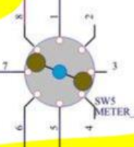
Can you refresh my memory on how that 2-pole rotary switch is drawn? Which pole connects to what as it's rotated?
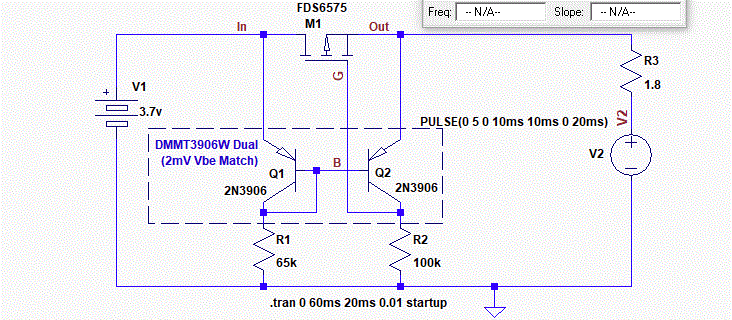
To get over your diode voltage drop problem, I was wondering whether a version of the "ideal diode" configuration could be used for at least the forward conduction path, and possibly also for the path back from the output voltage follower. There are not many ideal diode schematics on the web that would work correctly as signal diodes rather than power diodes, but this one might be interesting to consider, and doesn't need any power supply connection:
Ignore the LTSpice text. V1 would be the output of the first op amp, R3 the resistor feeding the hold capacitor (V2). I don't know about the availability of the dual matched transistor, but matching is definitely critical. This neat circuit works through the imbalance of the two Vbes due to the differing collector currents. It might be necessary to protect against large negative signal inputs, but the drop of a standard reverse-biased diode should be OK.
Can you refresh my memory on how that 2-pole rotary switch is d
Can you refresh my memory on how that 2-pole rotary switch is drawn? Which pole connects to what as it's rotated?
Those switches always confuse me, but the drawing is a pretty good visual, the balls rotate as the shaft is turned.
Its configured (with the mechanical stop pin) as 3 position switch ....times 2
In position one pins 7 and 8 & pins 3 and 4 are connected.
Position one connects the METER_OUT amplifier's output to U10As pin 3.
In position two pins 8 and 1 & pins 4 and 5 are connected.
Position two connects the METER_IN amplifier's output to U10As pin 3.
In position three pins 1 and 2 & pins 5 and 6 are connected.
Position three connects the METER_GR amplifier's output to pin 1 on R100.
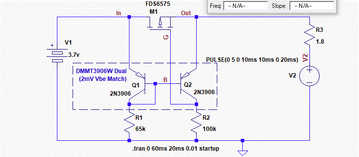
To get over your diode voltage drop problem, I was wondering whether a version of the "ideal diode" configuration could be used for at least the forward conduction path, and possibly also for the path back from the output voltage follower. There are not many ideal diode schematics on the web that would work correctly as signal diodes rather than power diodes, but this one might be interesting to consider, and doesn't need any power supply connection:
Ignore the LTSpice text. V1 would be the output of the first op amp, R3 the resistor feeding the hold capacitor (V2). I don't know about the availability of the dual matched transistor, but matching is definitely critical. This neat circuit works through the imbalance of the two Vbes due to the differing collector currents. It might be necessary to protect against large negative signal inputs, but the drop of a standard reverse-biased diode should be OK.
Interesting I have never tried something like that before, I will build up a protoboard and try it out, I have a stock of 2n3906s, but I will need to find a matched set. Thanks Boswell!
Yes, thanks for the memory jog on the switch. It's obvious now!
Yes, thanks for the memory jog on the switch. It's obvious now!
I had forgotten from when I last used the ideal diode circuit that if you want it to work down to 0V input, you need to bias the low end of the collector resistors at a couple of diode drops below ground, otherwise the transistor pair has no volts to work with. So it would need a power supply!
Made a few more face plate refinements... Attached file
Made a few more face plate refinements...
Attached files 1612 Vari-Mu Blue with White.pdf (52 KB)
Yes it does, should I get rid of the text label and just leave t
Yes it does, should I get rid of the text label and just leave the LED's?
Attached files 1612 Vari-Mu Blue with White no bypass label.pdf (52.9 KB)
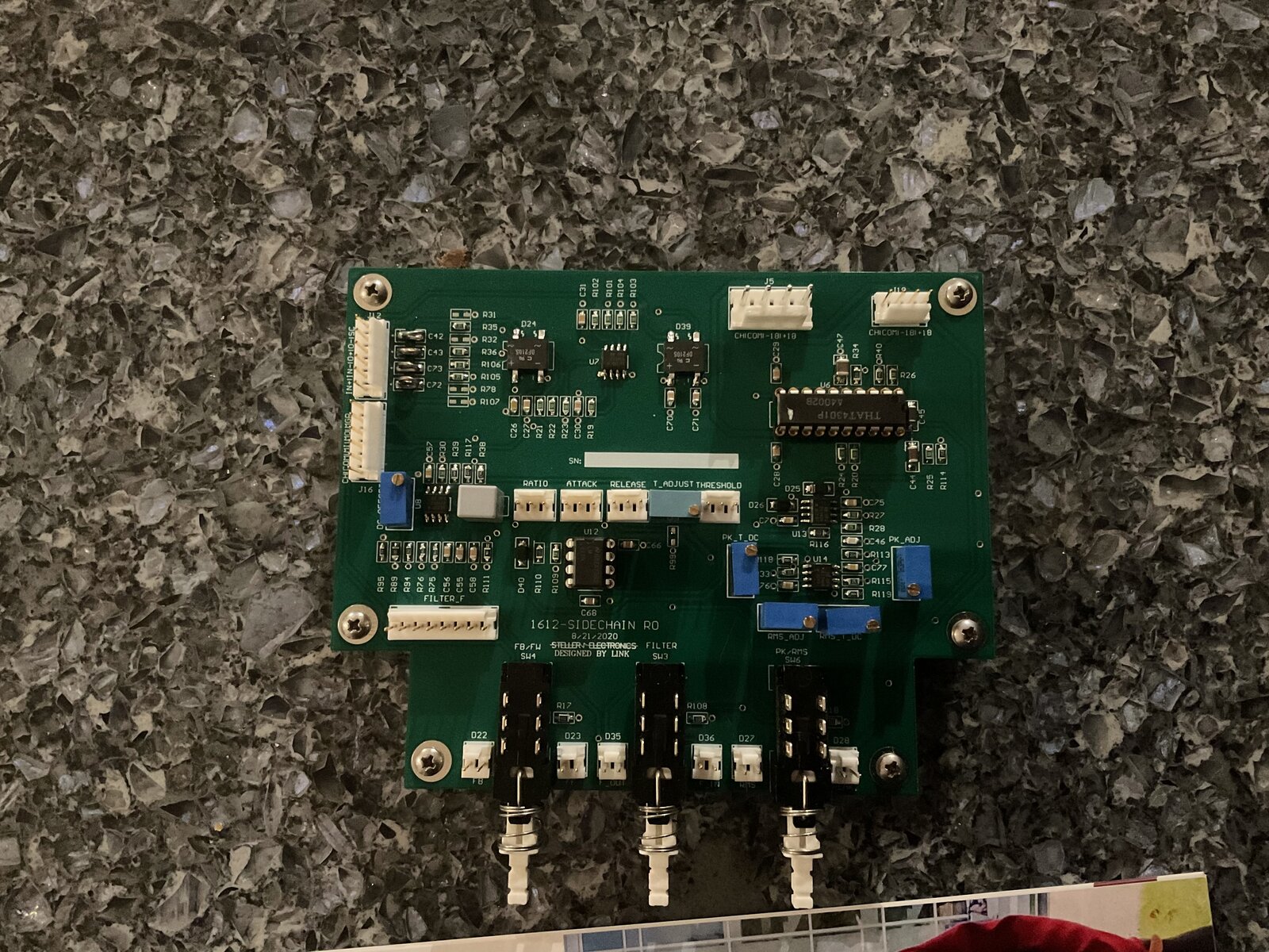
Finally got some desk time for the side chain board. Taking a b
Finally got some desk time for the side chain board. Taking a bit of time with this one as, I know the real work will be on this board. I opted to solder this one by hand instead of the toaster oven with solder paste, mainly because of small chunks of time I have at the moment.
I placed the caps last night, the OPA2134 opamps and some test points.
A bit of refinement to the resistors and I am in the parkbark of
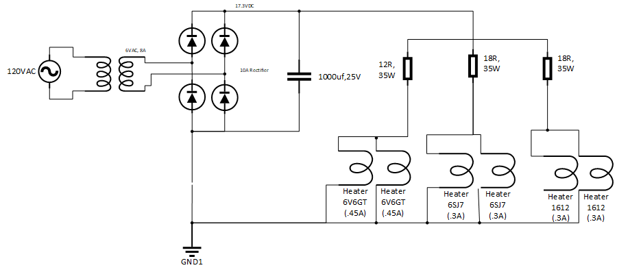
A bit of refinement to the resistors and I am in the parkbark of 6.3-6.5Vdc for the heaters. The two 6V6GT tubes need about 9 Ohms, the two 1612 tubes need about 9.5-10 Ohms, and the two 6SJ7 tubes need 12 Ohms.
Next issue is the current limit on the plate supply is triggering at a lower value than expected.
I thought when the 3.3 Ohm resistor (R5) saw a voltage higher then the VBE of the MPSA42 (T1) it would turn on T1. When T1 was on it removed the gate voltage from X2. So I was thinking:
0.6VBE / 3.3 Ohms = 181.2mA
At steady State I thought the maximum I needed was 80mA for all 6 tubes.
6V6GT
6SJ7
1612
Max Plate Voltage
315V
250V
300V
Max Plate Current
30mA
5.3mA
3mA
Max Current = 2 * 30mA + 2 * 5.3mA + 2 * 3mA = 76.6 ->~80mA.
So is this capacitor In rush issue? C6 is quite large at 470uF...?
I will try to catch the peak voltage across R5 with a differential measurement on the scope tonight.
Its getting interesting now ;)
With the heater currents, did you take the effective source resi
With the heater currents, did you take the effective source resistance of the transformer-bridge series pair into account when calculating the initial series resistors? I have to say I'm not a great fan of using dropper resistors from a higher voltage for heaters, as a single blown heater could cause the others to overvolt and be stressed.
I'll think about the HT current limit - sorry I'm a little pushed for time right at the moment.
Boswell, post: 468158, member: 29034 wrote: With the heater cur
Boswell, post: 468158, member: 29034 wrote:
With the heater currents, did you take the effective source resistance of the transformer-bridge series pair into account when calculating the initial series resistors? I have to say I'm not a great fan of using dropper resistors from a higher voltage for heaters, as a single blown heater could cause the others to overvolt and be stressed.I'll think about the HT current limit - sorry I'm a little pushed for time right at the moment.
No need to apologize, that last thing you need to worry about is my projects. I am so grateful for all your help already!
I don’t like the dropping resistor concept either, but for this prototype it’s gets me testing. I will need to figure out a solution to handle the in rush.
oh and yes the values I tweaked in circuit last night, take into account the effective source resistance. I basically played with the values until I found the sweet spot.
So I rewired the secondary of the heater transformer to to give
So I rewired the secondary of the heater transformer to to give 6VAC on the output and removed the resistors. There is a decent amount of capacitance after the rectifier(2010uF). There is a ripple that I would have liked to avoid, but for now, its closer to DC then most heater circuits I have seen.
I bought a new higher power FET for the output of the 225Vdc supply, I am hoping to test lowering the current limit and I would like to not destroy the fet in the tests ;).
At 650V, 24A, and 298W@25C I am thinking this will handle my abuse.
I managed to have a better look at the HT supply circuit. I take
I managed to have a better look at the HT supply circuit. I take it that the faint link between the anode of D21 and the FET source is real copper.
How are you gauging for how long the current limit is triggering on start-up? I would expect the 225V rail to climb from switch-on as C6 got charged with the regulator in limit. It should come out of limit once it got to something like 70% of its final voltage.
For the FET dissipation, I calculated that running at a secondary current of 110mA (half the transformer rating), the FET X2 would be dissipating about 9W when delivering an output of 225V d.c. That would be well within the range of the IPA70R600 on a suitable heat sink. However, I was worried that, since the regulator circuit is a limit and not re-entrant, if there were a short on the 225V rail, the FET would have to absorb the full output power of about 50W. Your new FET should cope with that, if it ever had to.
I have a slightly uneasy feeling about R3, the voltage adjust pot. I think you ought to limit its authority at the low end, maybe by halving its value and putting a 470K resistor to ground.
Boswell, post: 468173, member: 29034 wrote: I managed to have a
Boswell, post: 468173, member: 29034 wrote:
I managed to have a better look at the HT supply circuit. I take it that the faint link between the anode of D21 and the FET source is real copper.How are you gauging for how long the current limit is triggering on start-up? I would expect the 225V rail to climb from switch-on as C6 got charged with the regulator in limit. It should come out of limit once it got to something like 70% of its final voltage.
For the FET dissipation, I calculated that running at a secondary current of 110mA (half the transformer rating), the FET X2 would be dissipating about 9W when delivering an output of 225V d.c. That would be well within the range of the IPA70R600 on a suitable heat sink. However, I was worried that, since the regulator circuit is a limit and not re-entrant, if there were a short on the 225V rail, the FET would have to absorb the full output power of about 50W. Your new FET should cope with that, if it ever had to.
I have a slightly uneasy feeling about R3, the voltage adjust pot. I think you ought to limit its authority at the low end, maybe by halving its value and putting a 470K resistor to ground.
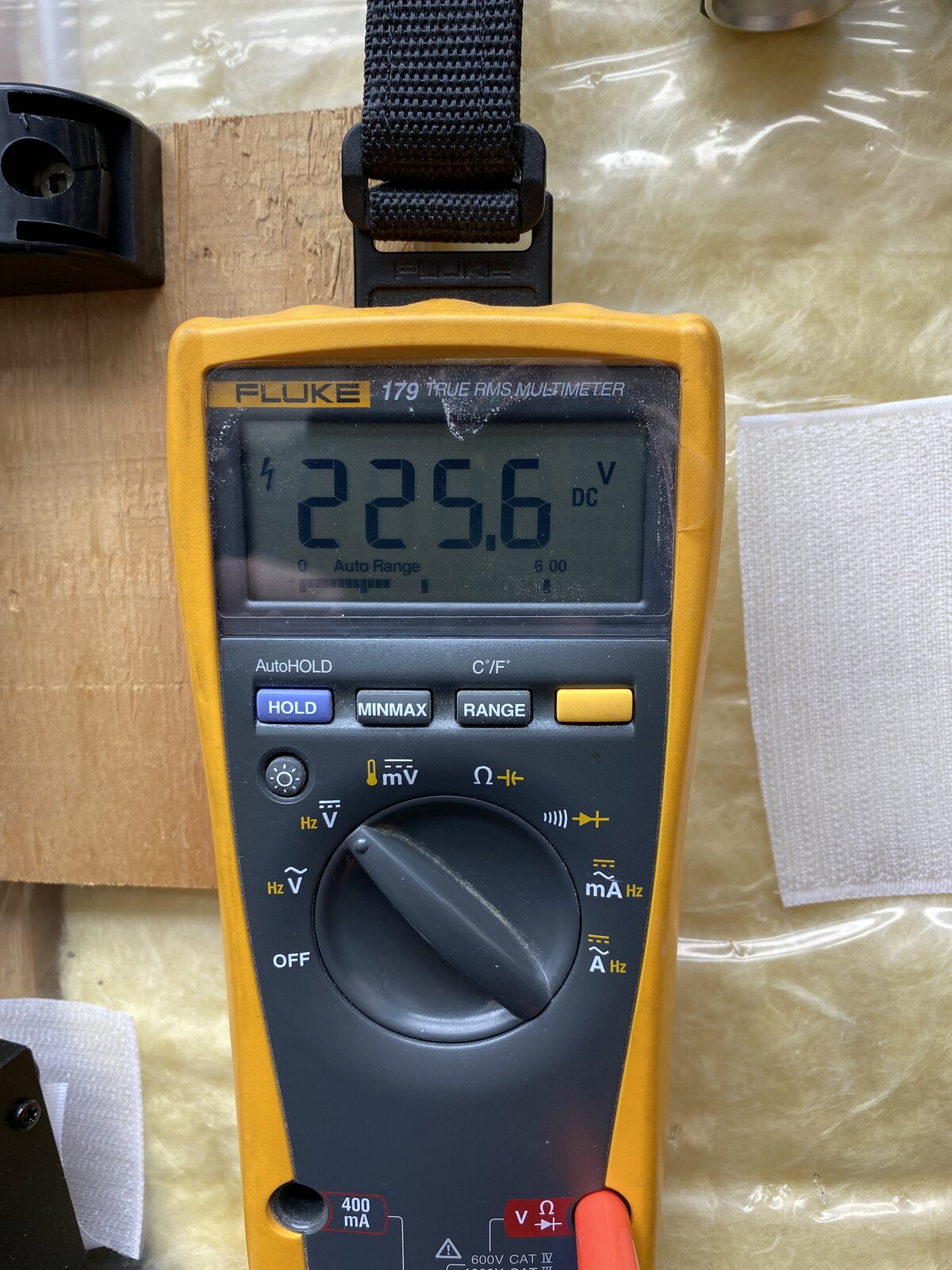
Thanks Boswell! The start up under light load( 470k resistor only) takes about 60 seconds to charge to the full 225V.
The heatsink is massive at the moment, but I will feel better moving up to the FCP150N65F.
For R3, your idea makes a lot of sense, it will help limit the dissipation across the FET if someone gets turn happy ;)
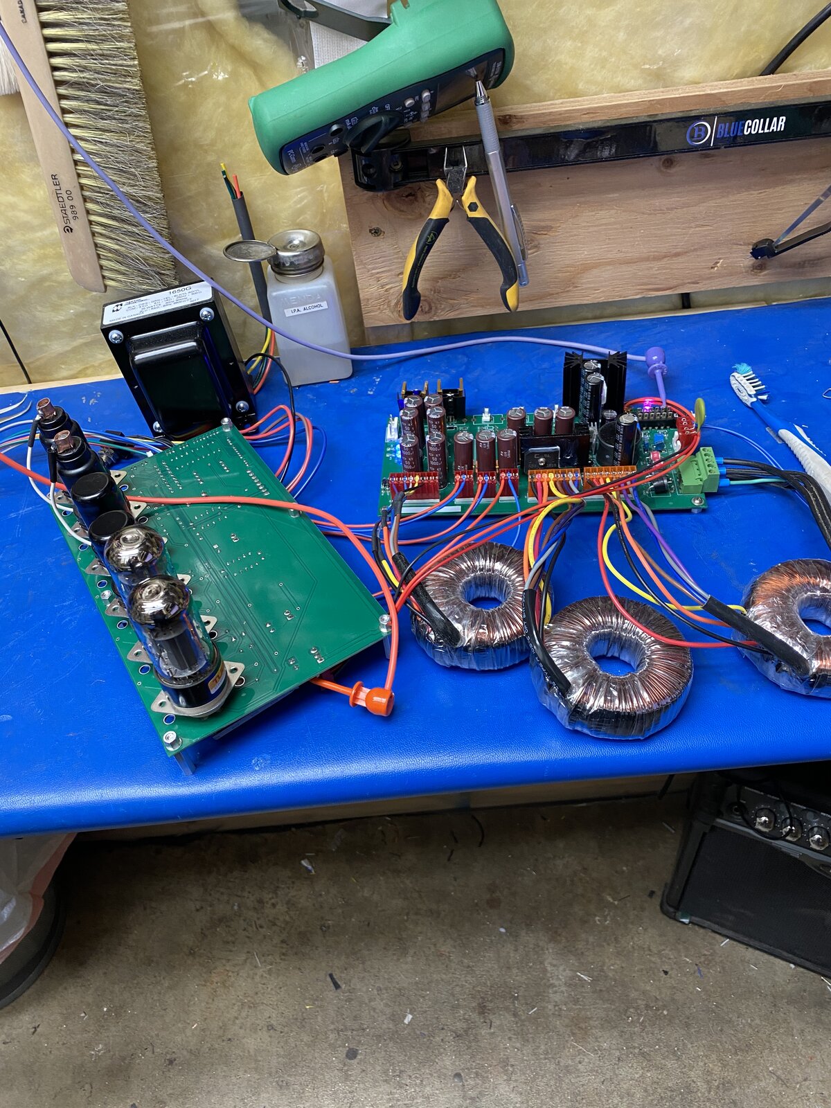
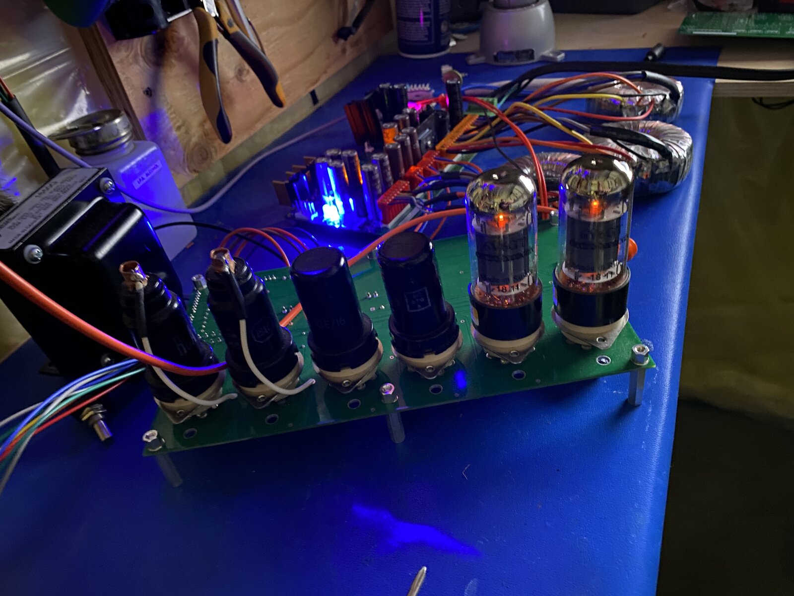
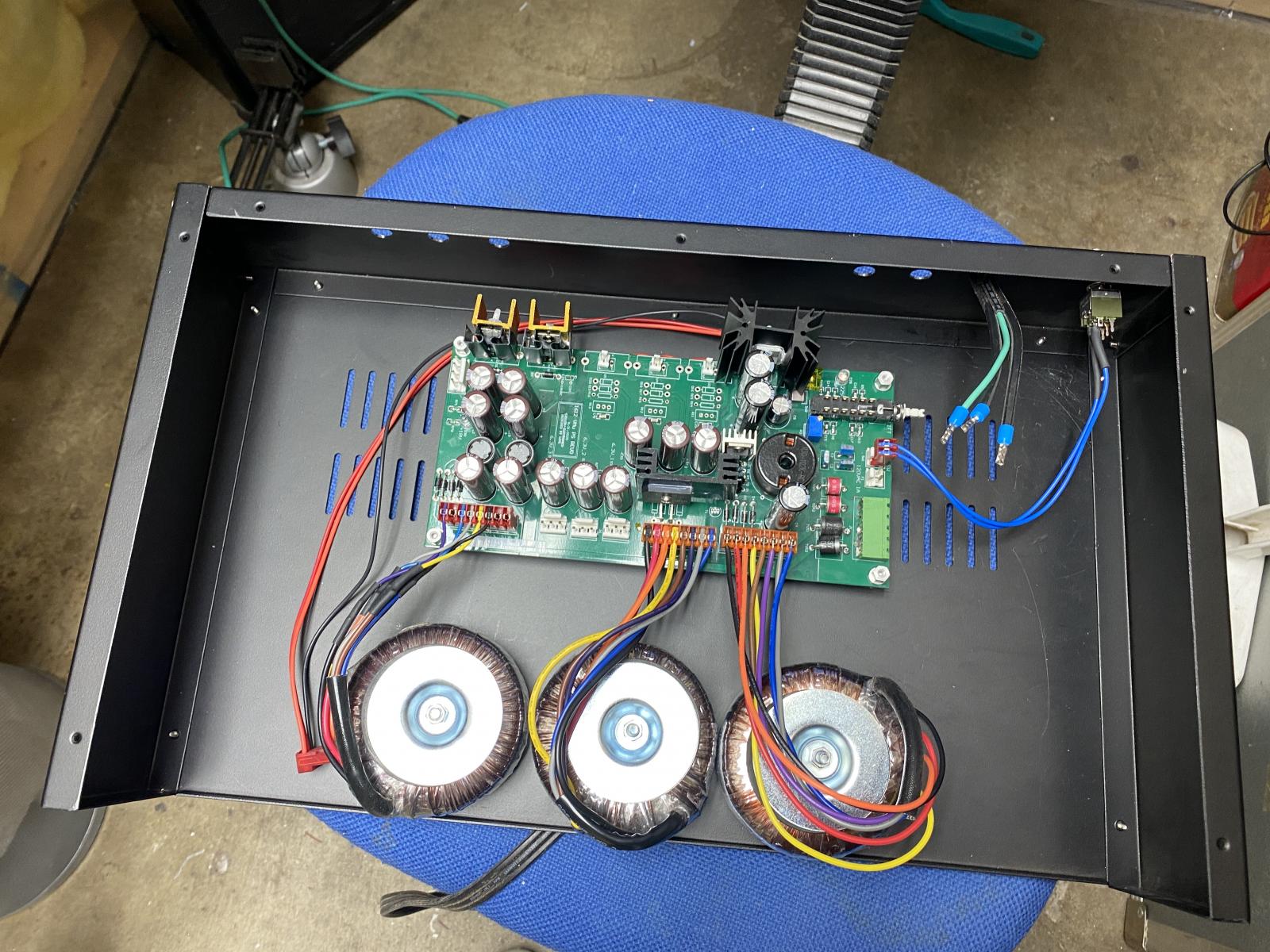
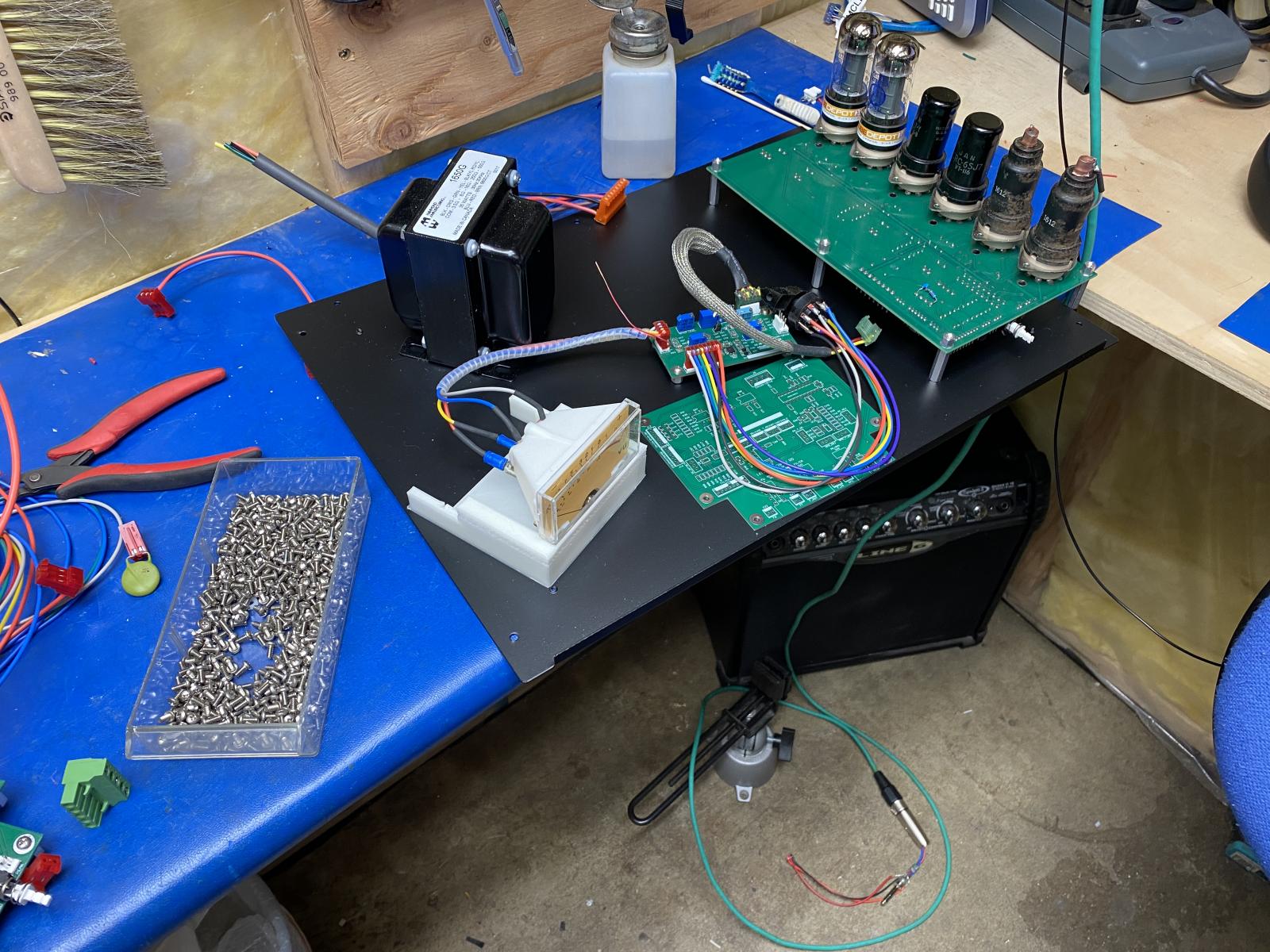
Well in between a a few repairs I managed to box up the power su
Well in between a a few repairs I managed to box up the power supply and a make power interconnect cable.
The cable was build by hand. The 225VDC leads are twisted, copper shielded and insulated. The 6.3VDC are also twisted, and shielded. The +18,-18 are also twisted and inside the overall copper 3/4" shield. THe cable is meant to go the compressor unit inthe rack directly above.



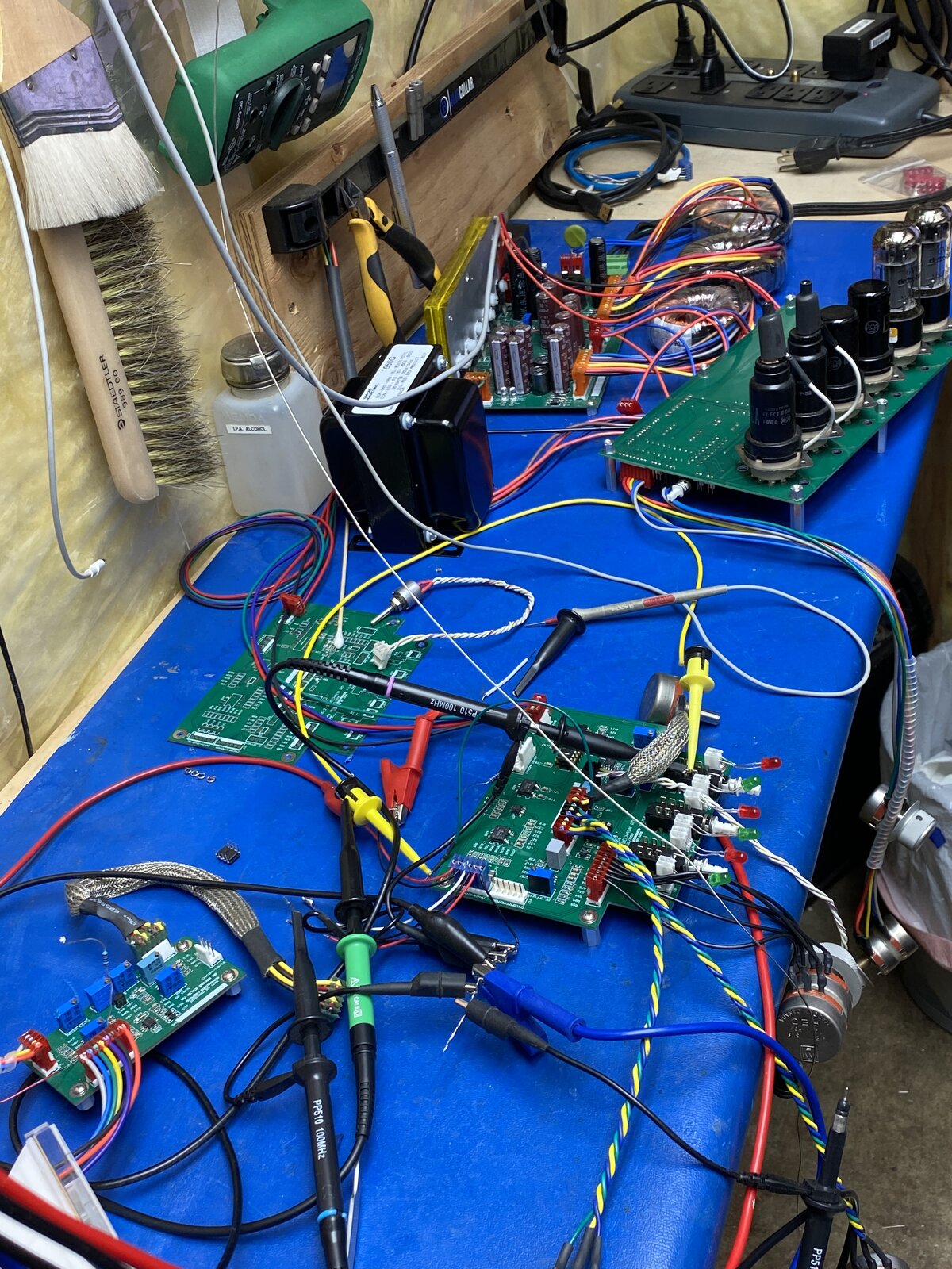

ok after a bit of fiddling around I manged to get it relatively
ok after a bit of fiddling around I manged to get it relatively close. The peak detector diodes seemed to exaggerate the problem with a 0.6V drop. So I put in a few schottky diode measuring about 0.4V and that helped. I then removed the DC blocking caps, and the pull down resistors. The gray comments by each components highlight the changes.
Attached files