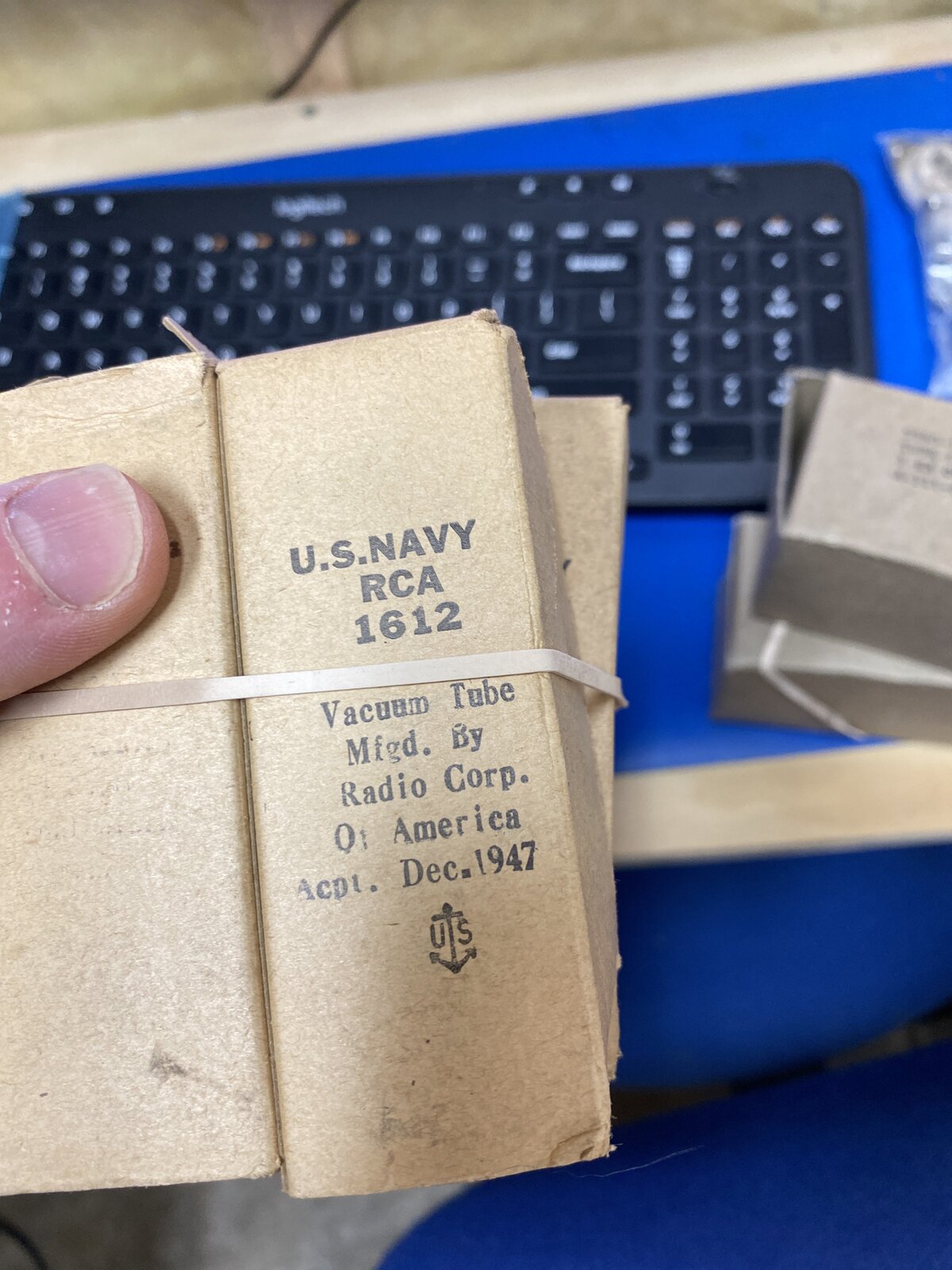
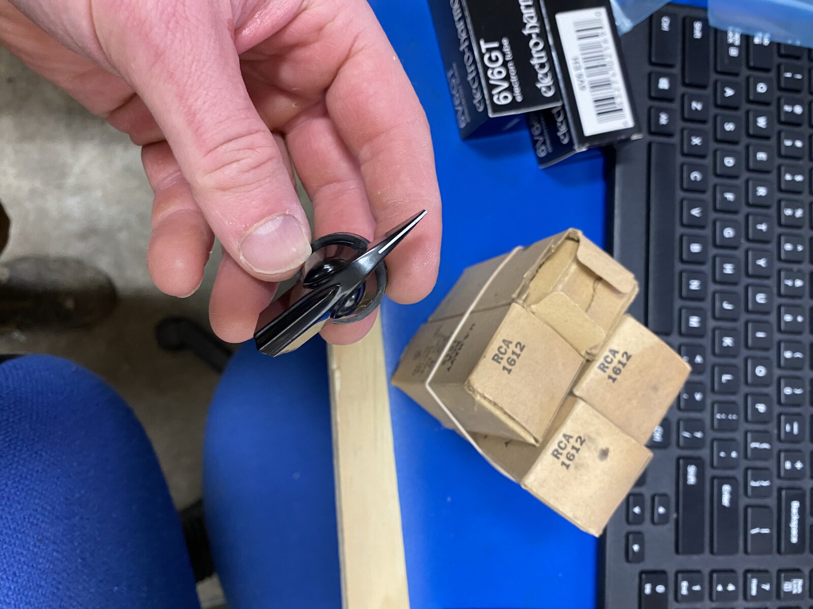
So I was so interested in the 1612 Tubes I got to play with... I started a hybrid design. The concept is a vari-mu style compressor using the 1612 as the front end after a Jensen XFMR. I am thinking of then running LA2 style buffer and driver amplifier into a Jensen output XFMR. But the side chain will be solid state and use either a LOG amp or a THAT audio engine.. Sort of a complex blend of 50's tech with more modern tech...
The panel below is the feature set that I would want...I interested to hear your thoughts or wants for a compressor like this...
Comments
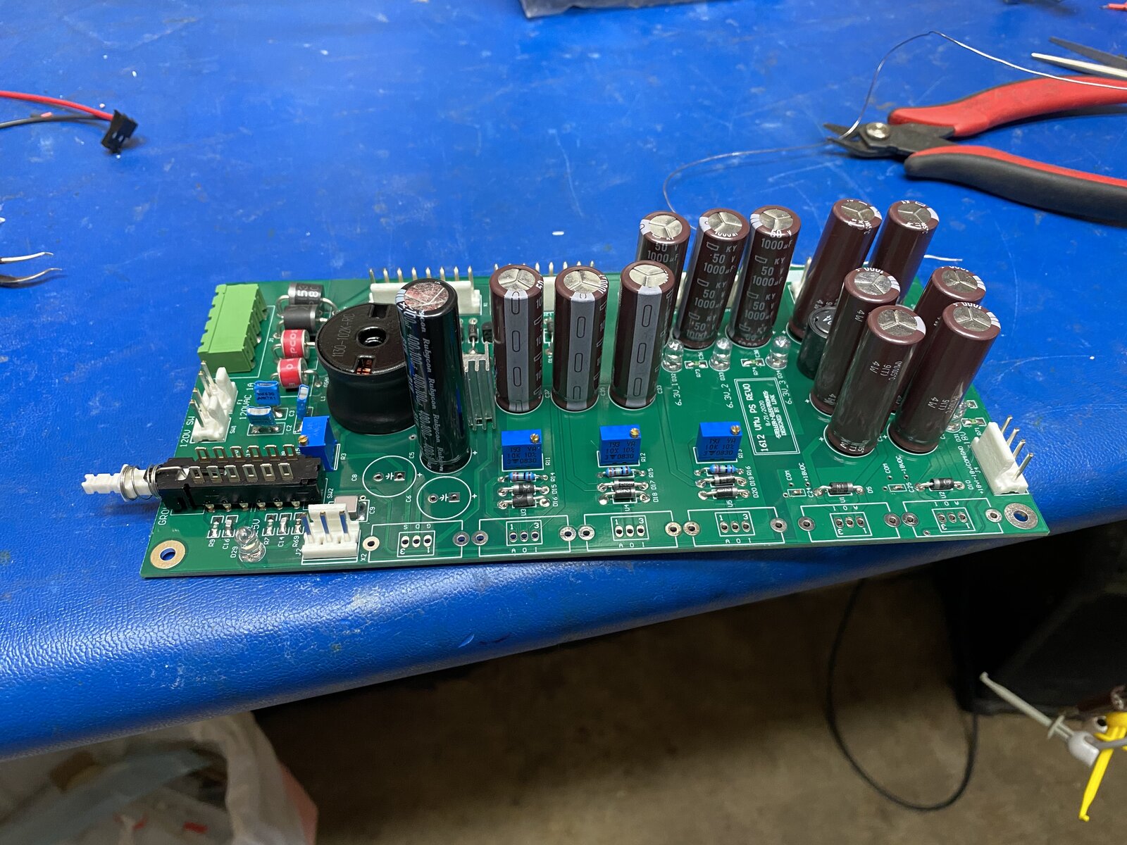
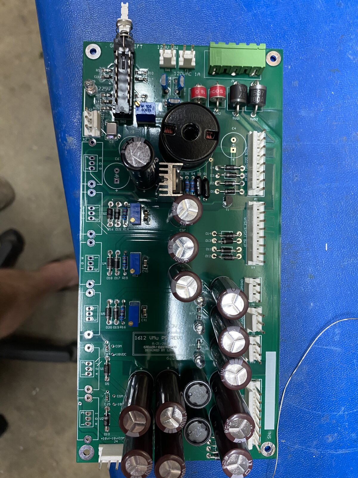
PCB's arrived yesterday! They look decent. I am still waiting
Thanks Kurt, I am pretty sure you have more than enough aptitude
Thanks Kurt, I am pretty sure you have more than enough aptitude and skills to handle this. I love the old circuits because they appear simple enough on the surface to suck you in. Then when your hooked you get lost in the subtleties of the design. I find it great fun to retrace the steps of much wiser minds...
Quick update- I have been having troubling getting to the shop t
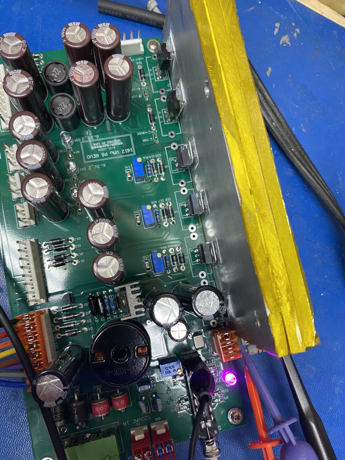
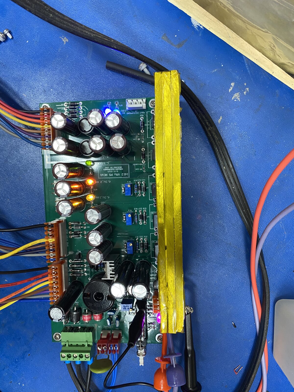
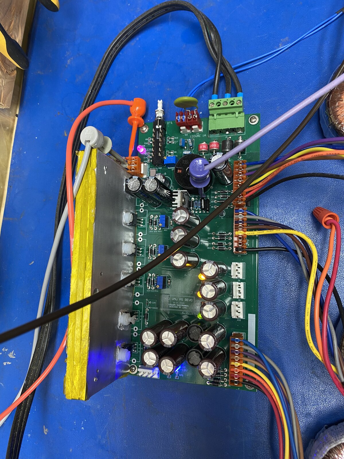
Quick update- I have been having troubling getting to the shop these last few days, but I did manage to finish the power supply build.
I had some 10 mm aluminium plate so I cut that up to be a three layer (30mm) 120mm x 80mm block with thermal paste in between each layer. I am using that as a heat sink for testing and possible the prototype. I have the 5 regulators and power transistor almost mounted to the heat sink via mica washers and thermal paste. I ran out of 6-32 nylon bolts so I am waiting on those to attach the lm317s for the heaters. The regulators and power transistors are soldered directly to the PCB. I forget to get photos last night.
I have installed the MTA-156 connectors to the three transformers and have started to test the regulated outputs. I have been just connecting one transformer at a time testing the PCB section by section. I started with the lightest load, the +18VDC and -18VDC section.
The +18VDC and -18VDC is working although the matching of the regulators could be better matched (17.84VDC and -18.02VDC). On AC coupling I can see about 5 to 10mV of ripple/Noise.. Hard to tell what is circuit noise and what is probing noise, I will need to load the output and take a more careful measurement.
I discovered a error in the transformer selection when I realized 6VAC will not be come 6.3VDC :whistle: So I swapped the transformer to another toroidal 12Vac 4A I had on hand. The LM317 are now working under light load. I still need to add the nylon screws to get the heat-sink attached. The TAB on the LM317 is connected to the output, so I don't want the outputs affecting one another.
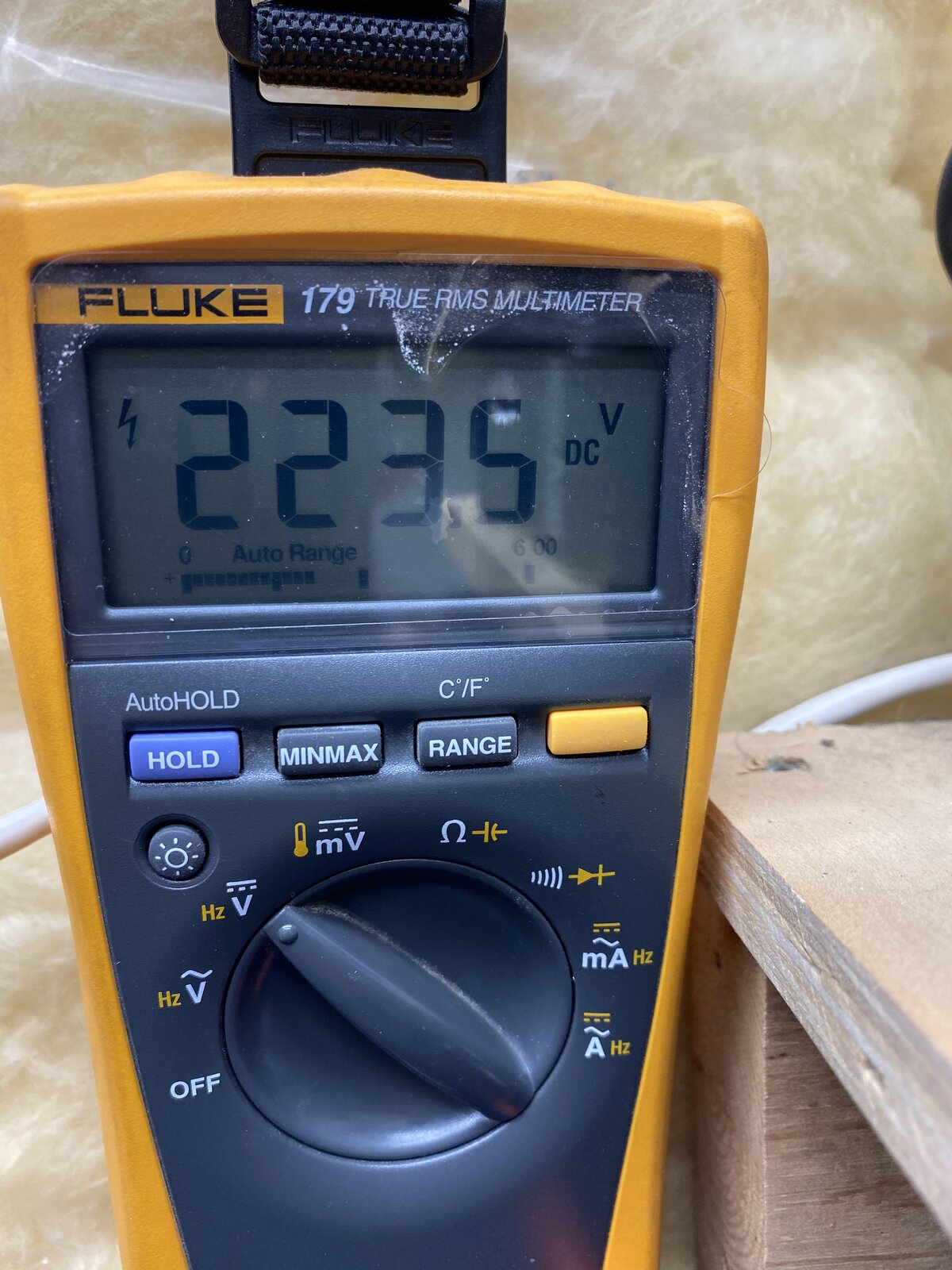
I have yet to couple in the 220VDC transformer, hopefully tonight. If there is issues that is where I have the greatest potential for fireworks :D
Boswell, post: 465411, member: 29034 wrote: Very impressive! Th
Boswell, post: 465411, member: 29034 wrote: Very impressive!
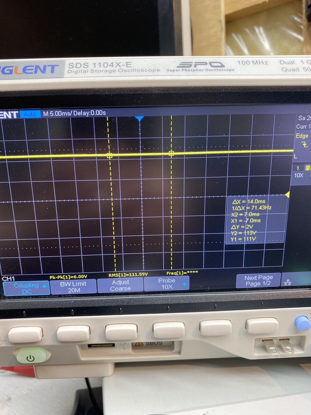
The HT ripple looks really low - was that on no load?
Yes sir no load - well 400k as a restive divider to protect my scope probe ... but no load yet.
Makzimia, post: 465412, member: 48344 wrote: Can't tell you how cool I find all this Link :). My 16 year old self is popping out in my head..
Thanks Makzimia .... lots of work to go...
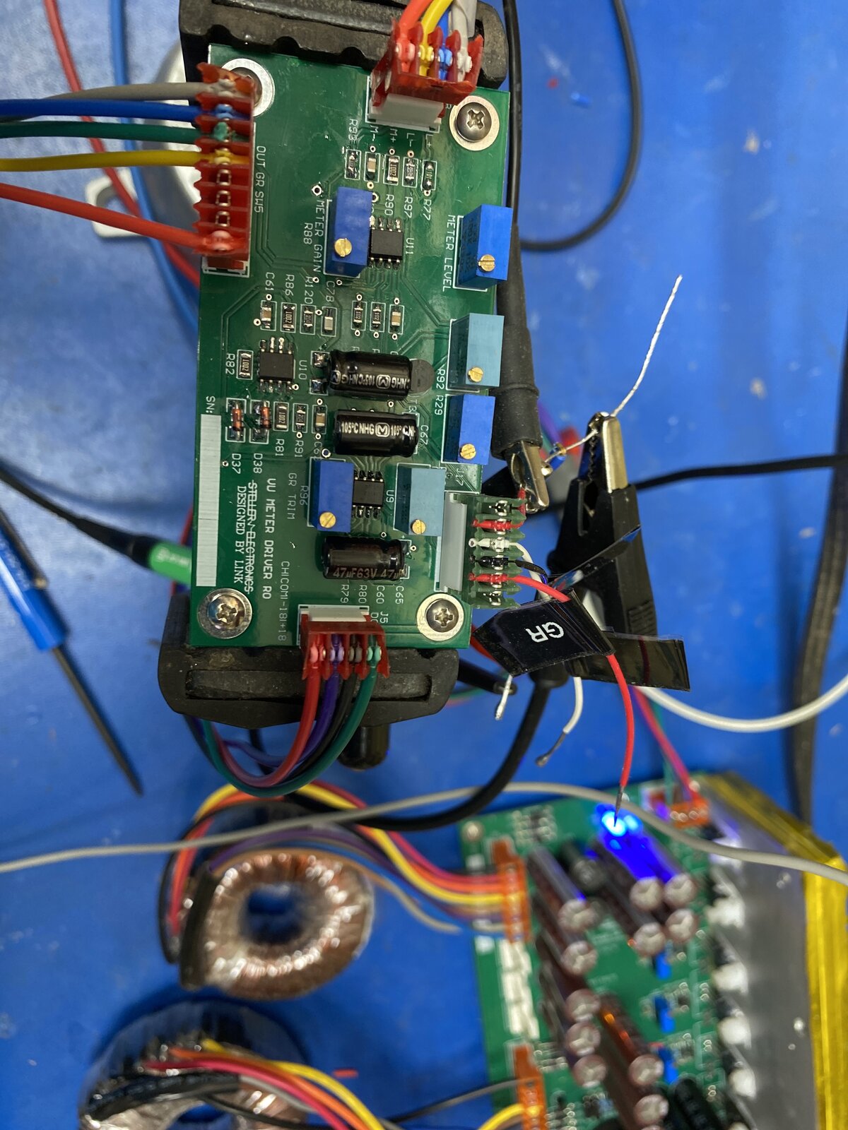
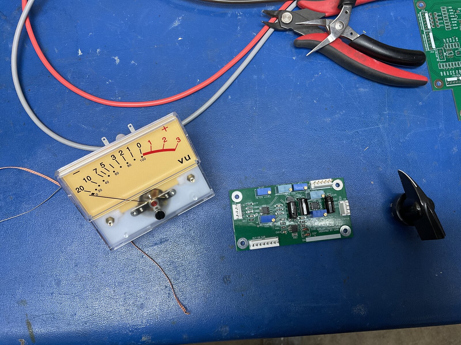
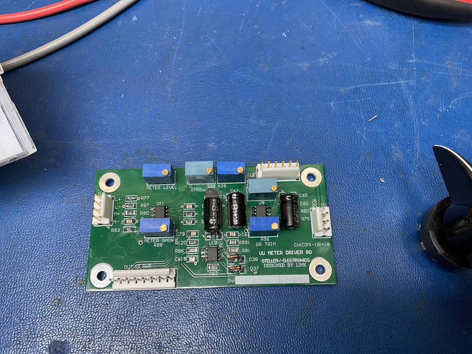
Tonight I finished wiring up the meter board, and had enough tim
Tonight I finished wiring up the meter board, and had enough time to test the output a bit... still tuning my circuit for the new vu impedance but it’s definitely alive!
Attached files 63220345580__8D280B76-0099-4478-88B8-6BEF1CB20210.MOV (3.9 MB) 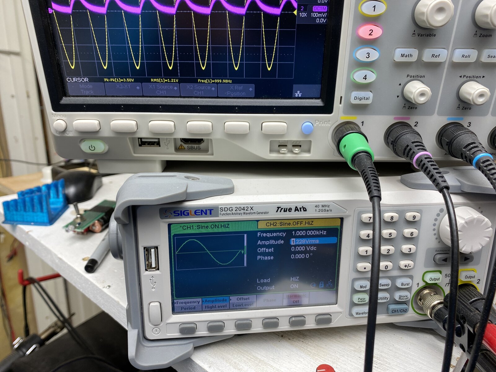
Well the Amazon Meters are proving a bit challenging. I tried
Well the Amazon Meters are proving a bit challenging. I tried these guy out:
https://www.amazon.ca/gp/product/B088WLJJZW/?tag=r06fa-20
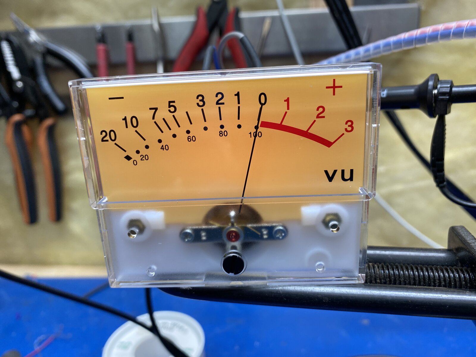
But they arrived poorly packaged and the black plastic retainer was cracked on one of the units. Not sure if that is related to the current issue I am working through, but it might be. Right now I can get the meter to move without issue but there is a significant non-linearity in its scale.
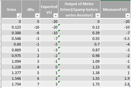
If I set 0VU on the meter to 1.228Vrms, the meter moves perfectly every time to 0VU when I turn off and on the 1.228Vrms signal.
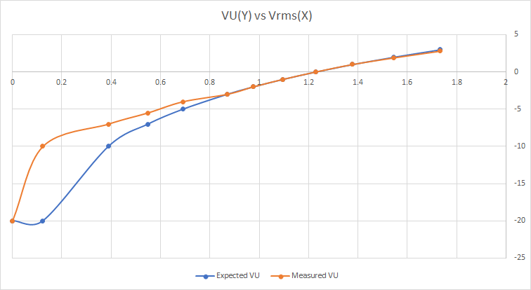
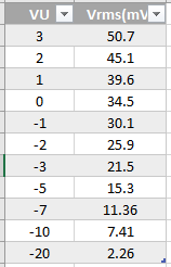
If I then set the source to 0.388Vrms expecting the meter to move to -10VU it moves consistently to -7VU. I took a few measurements to explore this non-linearity. I measured the output of my circuit at output final opamp before the series resistor feeding the meter movement. My scope was used to verify signal generator meter. I tuned the circuit to have 0 gain. The circuit appears to be good.
The graph is not in log scale, Excel doesn't like 0's in log scale. From the graph you can see the meter is reading higher that it should be on the lower scale but better on the upper scale.
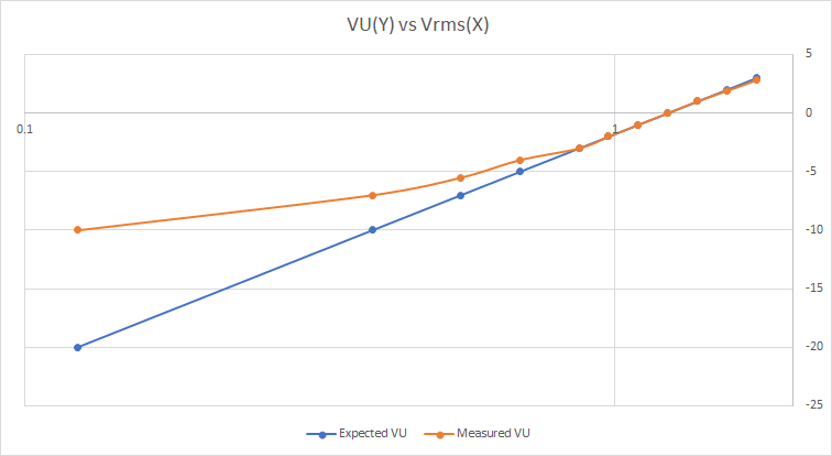
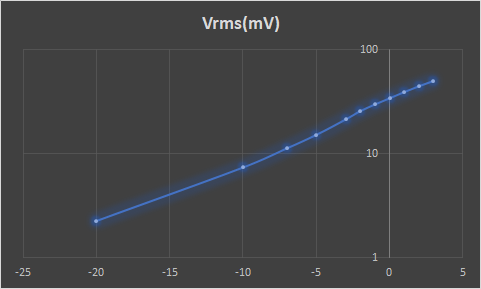
If I remove the 0 point and set the scale to logarithmic I get this:
Could it be static build up? or just an unbalanced movement?
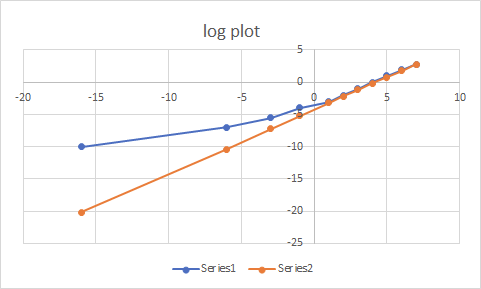
Yeah, that does look a bit odd. I've tried a quick re-plot of yo
Yeah, that does look a bit odd. I've tried a quick re-plot of your figures with log ordinate and linear dBu abscissa, and then scaled the input so it lies on top of the reading for the higher amplitudes. The higher readings look OK, but it shows things start to go wrong at about 0.5Vrms (a diode drop?).
I made a correction to the 0.338 Vrms meter figure to bring it back on to the straight line, since it looked like a typo.
Sorry, my series colours are reversed compared to yours.
Did you ever check with the scope what the waveform looked like at the top end of R100 (the amplitude calibration pot)? The PWM should be reasonably linear with sine-wave input.
Does this meter have an ordinary direct current movement., or has it got rectifiers inside? What do you see if you feed the VU meter with a multimeter in parallel from a controllable d.c. source?
Thanks yet again for your time and help on this Boswell, it very
Thanks yet again for your time and help on this Boswell, it very much appreciated.
I made a correction to the 0.338 Vrms meter figure to bring it back on to the straight line, since it looked like a typo.
Yes it was entry error-but I may have made a "Reado" and entered .388 on the generator ;)
Did you ever check with the scope what the waveform looked like at the top end of R100 (the amplitude calibration pot)? The PWM should be reasonably linear with sine-wave input.
I did quickly look at the the top end of the R100 pot, and peak detector is working as expected I did play with C69 to follow lower frequencies. So that cap is now 10uF. So it is essentially DC feeding the meter movement.
Does this meter have an ordinary direct current movement., or has it got rectifiers inside? What do you see if you feed the VU meter with a multimeter in parallel from a controllable d.c. source?
No documentation came with the meter, I am not sure if it has a rectifier inside, I have not taken it apart yet... Digging online it appears to be a TN-73 VU, some forums mention it has a rectifier, some say it needs one. Only one way to find out.
http://www.meterexpert.com/e/VU_57.htm
I did quickly try it with a DC source when I first got it, and verified a swing, but did not measure or record the voltages. I can do that tonight and check the linearity of those readings.
Good Thoughts for sure!
Thanks!
ok the plot thickens... With my bench supply connected through a
ok the plot thickens...
With my bench supply connected through a 680k resistor in series with meter movement, I measured these voltages across the meter.
Pretty Darn linear, the deviations are likely just measurement error.
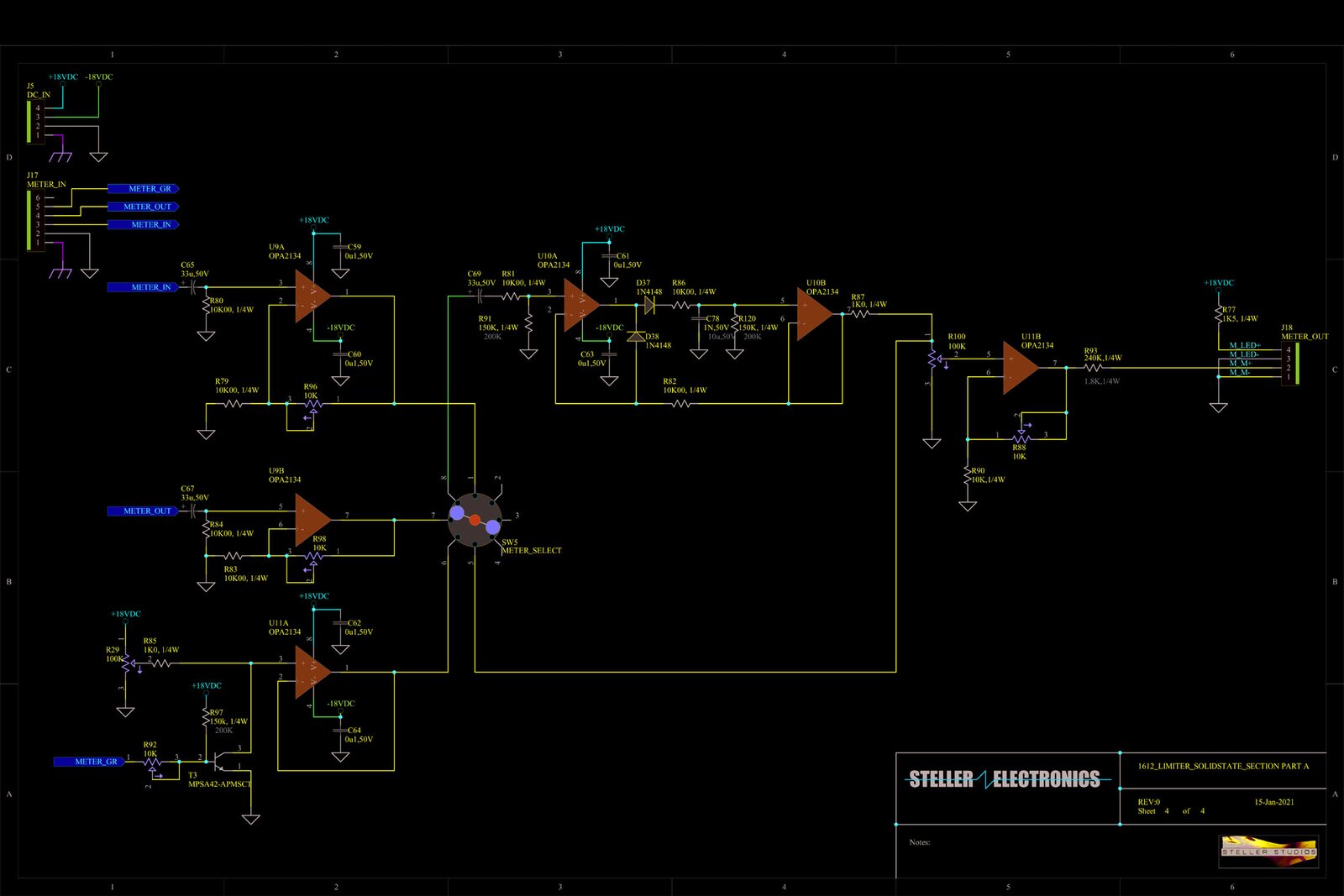
So what in the circuit is causing this non-linearity... I checked for loading watching the output of the the last opamp (U11B Pin 7 ) with the meter connected and unconnected. No change in the voltage. The peak detector is DC at 1K, with the 10uf cap in there the ripple at 10Hz is very small. Is this phenomenon the discharge time of the 10uF?
What puzzles me about the schematic (along with the way you say
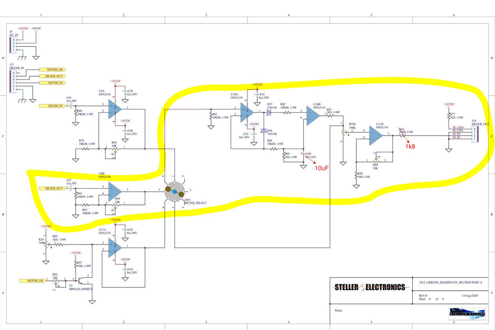
What puzzles me about the schematic (along with the way you say it behaves) is how amplifier U10B gets its negative feedback. As it stands, it's a comparator whose output swings rail-rail. In conventional peak trackers, the second op-amp is usually a voltage follower, but I realise this one is not the conventional configuration.
Truly a "Doh" moment I spotted that mistake earlier it se
Truly a "Doh" moment I spotted that mistake earlier it seems, the PCB is correct after all. I Just never posted the final Rev 0 schematic here. This the problem with time gaps in projects ;)
so that explains why it works, but its doesn't help explain the non-linearity.





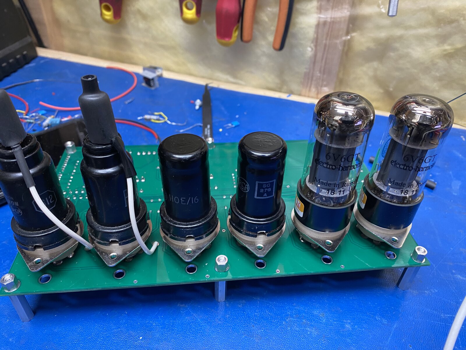

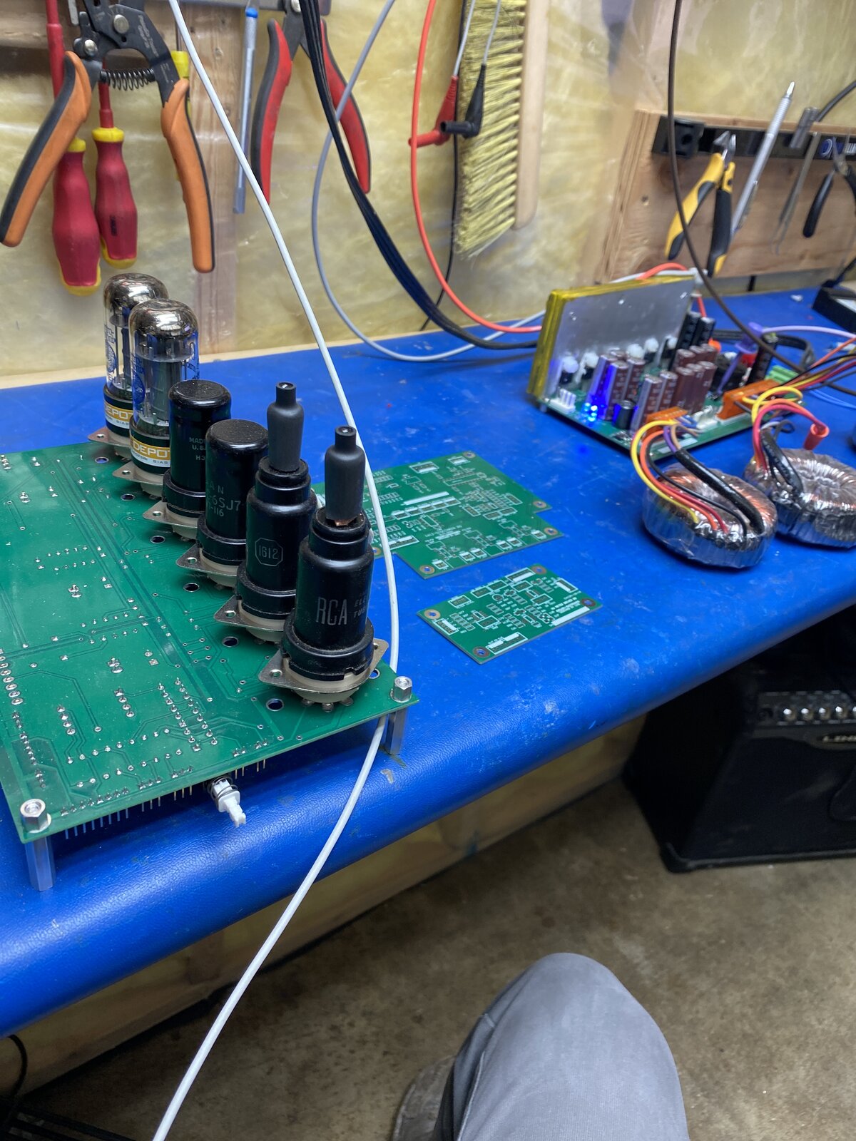
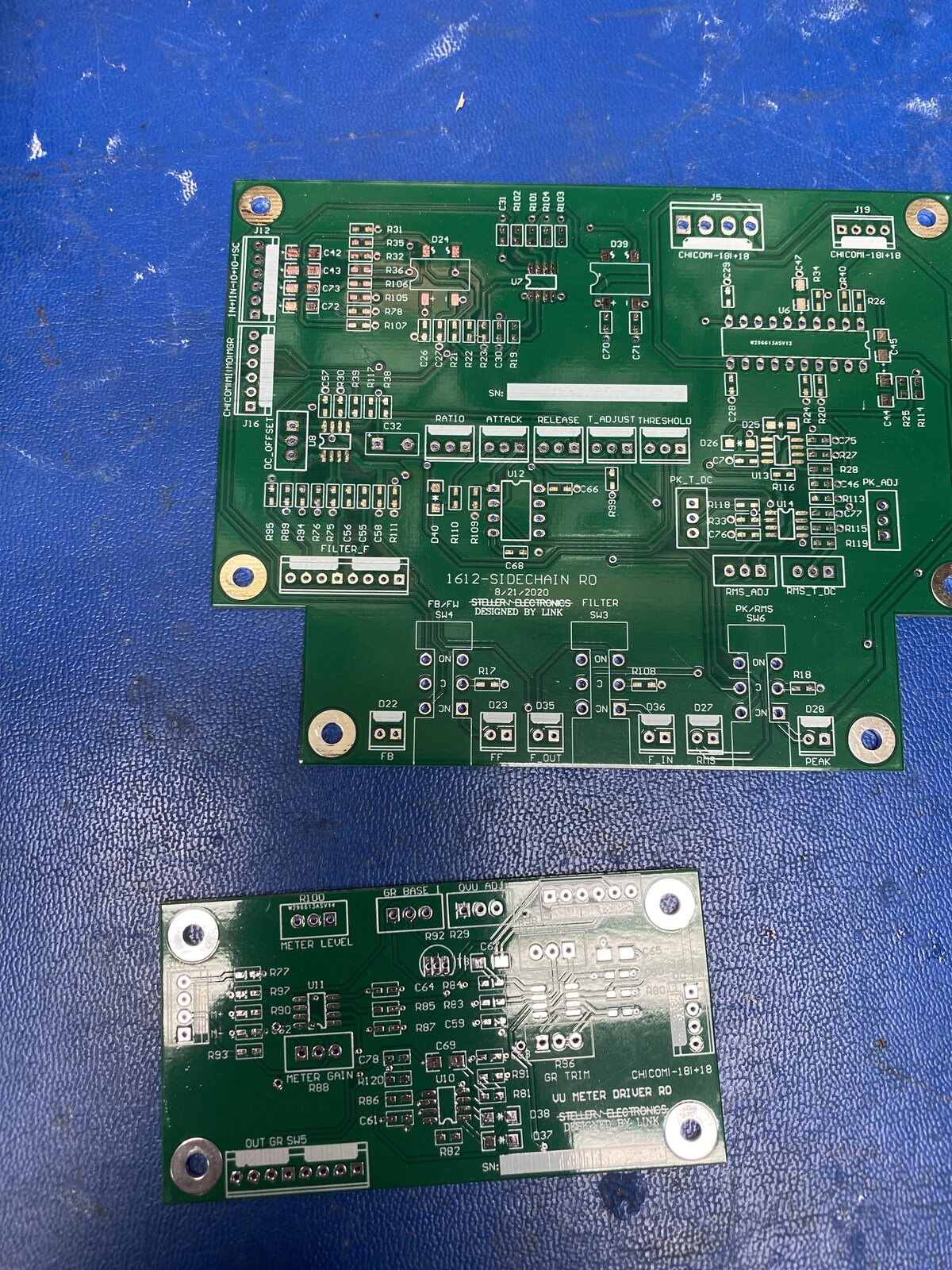


Boswell, post: 465264, member: 29034 wrote: I would put the fatt
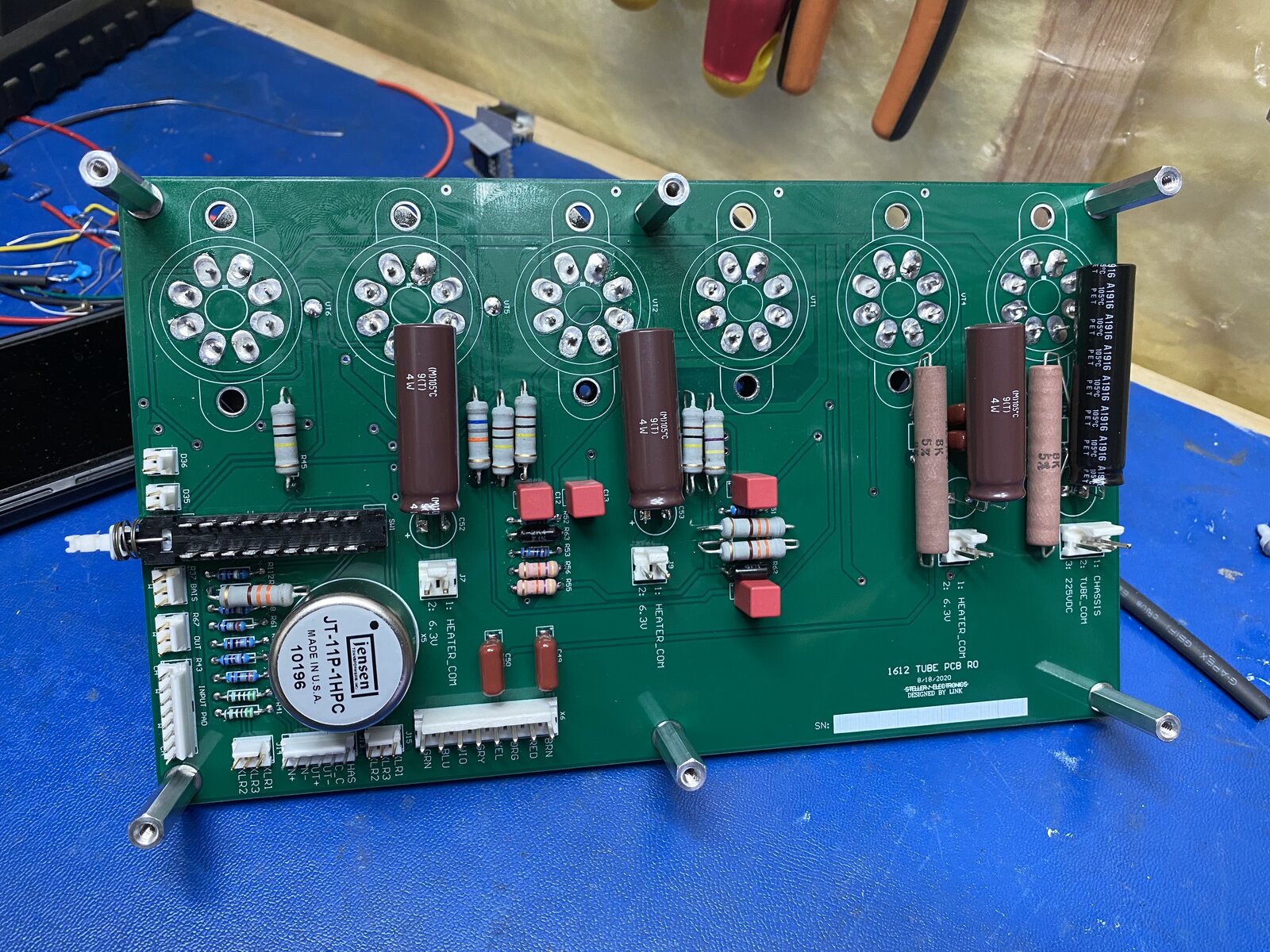
Thanks Boswell good point ....the Heater traces are 40mil right now.....there are two tubes per LM 317 so slightly less than 1A per LM317. The tube board and PS will be 2 OZ copper.
The on board transformer is line input transformer, but bigger pad is generally better for rework...
Yes sir, I am trying to stick be hunk of metal on those regulators. ;)
They Do, as did the Gates 39B and 39A. I need to test this with the Jensen impedance ....I have a similar issue with output transformer.
Thanks Boswell, Its so great to be able to pick your brain, I really appreciate your input!