Hey everyone, my buddy ask to help him w his home theater. So I figured I'd add a thread to keep all the construction and acoustics related to it in one spot. This isn't my project so I don't have any control other than the power of suggestion, but I thought this would be a great opportunity to learn some stuff as this process goes on, and also have a documentation of some of the inevitable hangups, so maybe somebody else in a similar circumstance could have a resource. This is just at the brainstorming phase overall. Anyway here's the basics:
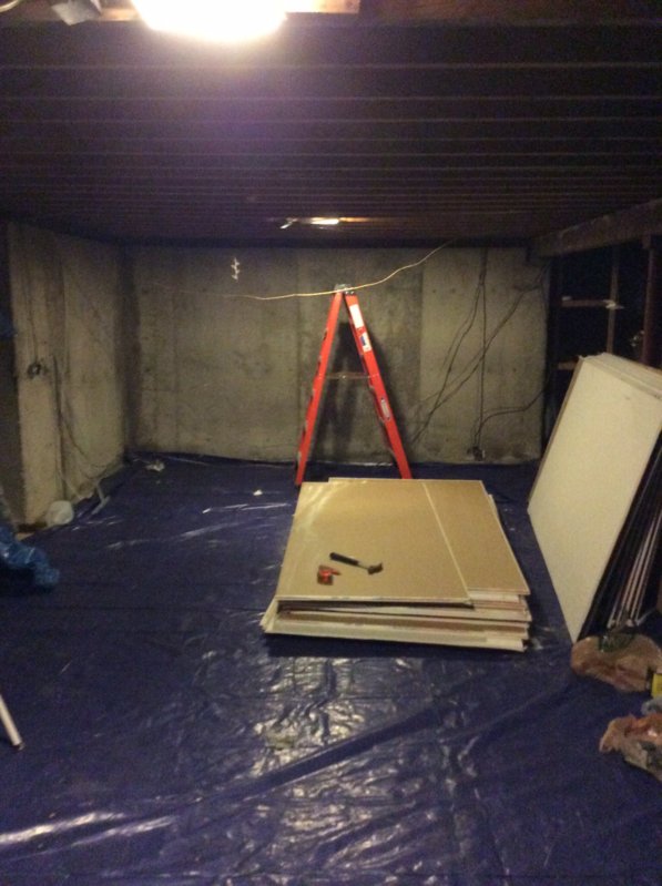
We're in the planning phase of a basement home theater/kitchenette,in a 7'2x15x30 and 7'2x12x20' (rough) area. It's a walk in basement, 2x8 12"oc, 2x4 walls, and foundation in some areas.
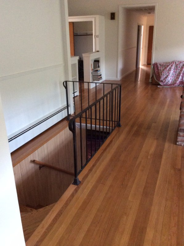
This is the 'front'.
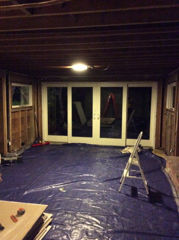
That is the 'rear' walkout part of the basement 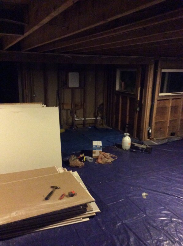
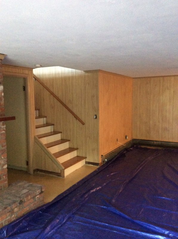
That is looking a little left from the rear door.
The plumbing you see is for the existing bathroom/shower, that will stay.
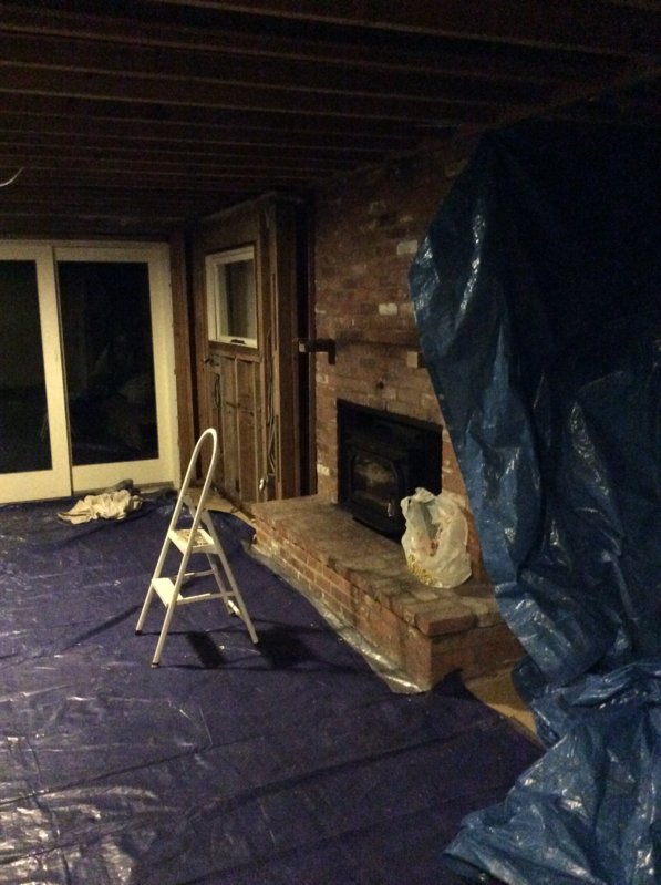
Ill attach some shots of the place so you can get a better feel. Anyway.
The ISO requirements/expectations would be met if a person could comfortably go down with an acoustic guitar and sing along at an average folk style volume. When 5 cizek speakers and 2 15" custom (it'll be a first for me) subs, powered by haflers, its gonna just get loud down there when the audio video mayhem happens, and it'd be absolutely ridiculous to have expectations of doing much against that, and with around 10k budget for the raw materials, it's gonna add up fast, although the existing physical space limitations, are really the determining factor in the overall design. So the overall idea is to just make a nice comfortable place that offers privacy, and as much isolation as possible, given the existing conditions.
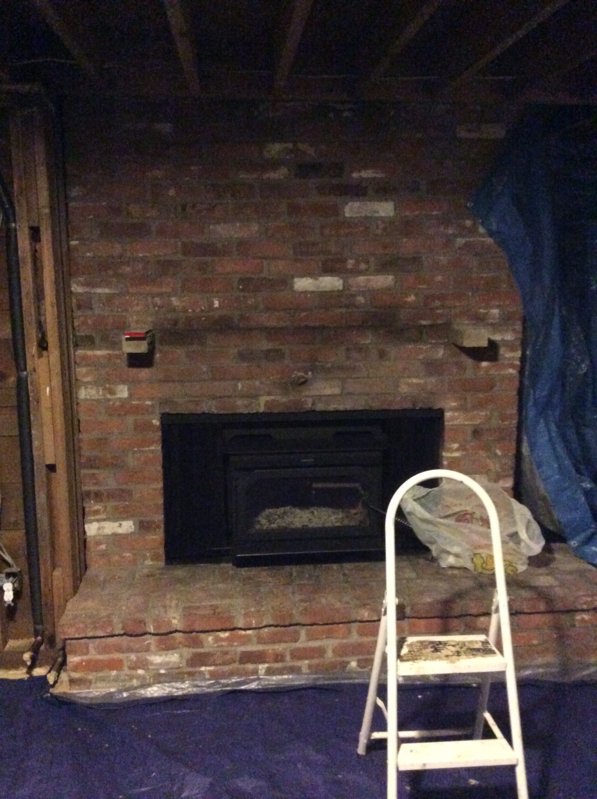
Since there's a fireplace (see pic) that runs right upstairs, and a fairly low ceiling height, it's seeming that the best option is basically similar to the example build in rods book, with a channel system for the ceiling, and double walls, stains concrete floor/area rugs. My thought was to use RSIC-1 clips and hat channel, in place of the RC channel as described in the book (ed1). After a lot of thought, that seems like the best compromise, as they can support 3 5/8" layers of drywall, and with the possibility ofgreen glue in between it seems like the direction to think towards. If the fireplace was going to be removed, the house jacked up 4 ft, and the windows all custom built, then the semi independent ceiling resting on the walls would be the way to go. but working that type of ceiling design in this just seems too elaborate, and unnecessar, although I'm of course open to any suggestions. Even though relative to the rsic-1 clips it's cheaper, I think the ceiling height would be the limiting factor anyway, as space is premium, especially the ceiling.
I found http://www.pac-intl.com and they seem to have a lot cool variations on the rsic-1. They got back to me after about 3 days, when I asked them about spacing/pattern for 12" oc as it's not listen on the site, they responded w a graphic, and saying to use the figures for 16 oc. I would obviously have to figure in the extra clips.
Does anyone have or know anyone who has had experience with this company? They have a thorough website and offer test data from riverbank laboratories.
Also they have a putty to put over outlets, this could prove very useful as there is an outlet that protrudes through the floor deck above. Seems kinda pricy, but what isn't, when the words studio or custom are involved. Are they/ that putty type in general effective, even if overpriced? We only would need a few. Are there better alternatives?
Anyway, now that everything is down to the studs, we re gonna do a sound test w some amps and some speakers to see what we got going on, especially regarding the fireplace. Again do to the limitations it's not expected that a bomb shelter is gonna be there, but it should be a fun project overall, and a great chance to try my brand new makita 12 sliding miter saw and stand! Gonna get the best blade I can afford for my new (very heavy) baby, thinking forrest chopmaster. Got the stock blade which got good ratings as a 'useable' blade, for any rougher everyday tasks, and a freud (researching better) big box blade for the good old framing lumber. After years of borrowing, I finally pulled the trigger, w the makita being the far more practical choice for my weekend warrior self, than the uber saw the festool kapex. (I drool over well engineered things :)) ramble over.
Random Problem areas I can see right now are the beam, which would prob be buried in a soffit used for trapping and lighting. Also the staircase to the left (which I hope I have a pic of). Maintaining ISO in a similar staircase is in that chapter, but this one is a little different, as is the overall design. And def a very questionable area of the project.
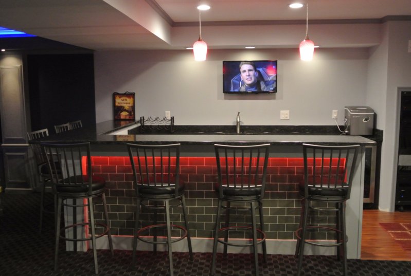
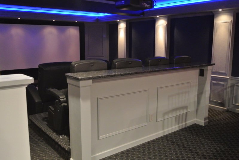
Any thoughts and suggestions are very much appreciated, the pics of the finished theatere are of one I found on line that was similar in shape and size, so something of a rough template, but w the doors wide open. Thanks!
Tags
Comments
By regulation I am talking about voltage regulation. A steady st
By regulation I am talking about voltage regulation. A steady state of 120 volts will suffice to keep the surges and brown outs to a minimum. As long as no circuit is sharing a neutral there shouldn't be problem with a fault on any single line. I dont think that class "D" amps fire much 'DC' back towards the source in event of a blow up. Also be aware that the phases in this set-up should be balanced carefully and all power amps should be on the same phase. Unless theres a transformer supplying the facility and isolating.
Did some drawings of the bass trapping insulation location and o
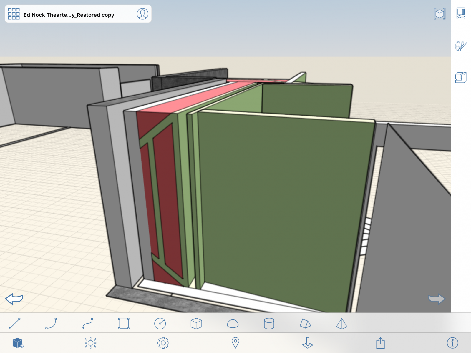
Did some drawings of the bass trapping insulation location and orientation. The framing isn't in these drawings for clarity. It kinda looks like a watermelon lol, but the green/yellowish is 2"/4" 703 (3psf), and the pink is standard R- value insulation. In the BTLP book it says the insulation is stacked, but not to compress it, so I'm guessing its stacked on its sides??? Not exactly sure about the details on that. Unfaced insulation wouldn't support itself hanging. the main area with the triangle shows the main listiening position. Listens will face the big green wall which will have the screen in front of it. The main bass trap is shown behind the screen wall to the side. That long bass trap is in the hallway area, it will be broadband or most likely tuned with stained wood slats.
For scale. The front wall sandwich is 2' deep from ISO wall to front face. The trap is about 3'deep x 8', and the long bass trap is 1.5' deep, and 15' long. It would be great to have another one of those on the other side wall too, but space is limited to a point. This should offer us some great control over the fun, sub/lows when tuning the room for maximum carnage ;)
It's 4" 703 everywhere except the hall bass trap, and two spaced layers on the front screen wall. It's 2" 703 in those locations, at least up to this point in the planning. The spaced layers is becasue that's basically how an example in the BTLP has it, but in that picture, there's also wood slats. So I'm not to sure why a 2" space then 2" layer was used, instead of one layer of 4". I'm wondering if one layer in is to dampen the slats, while the next is the start of the 'bass trap'? not sure how 2 layers with an airspace compares with one 4" layer.? So there are some questions still about the specifics, but it's nice to be able to see it out on screen.
Also I'm thinking of possibly going 'superchunk' style in the bass trap corners instead of the straddled panel with fluffy behind it like I drew.
Also, looking at it, I think the left corner of the screen wall could also have a superchunk or other style corner trap. I wanted to show how the floor/wall and wall/ceiling corners are going to be treated. I'll have to draw that in next, along with the ceiling cloud array...
" The spaced layers is becasue that's basically how an example i
" The spaced layers is becasue that's basically how an example in the BTLP has it, but in that picture, there's also wood slats. So I'm not to sure why a 2" space then 2" layer was used, instead of one layer of 4". I'm wondering if one layer in is to dampen the slats, while the next is the start of the 'bass trap'? not sure how 2 layers with an airspace compares with one 4" layer.?"
You ever get that figured out? I do not have the second edition so that may be the reason why I do not have it.
No not yet. I tried to calculate it using the multi layer absorb
No not yet. I tried to calculate it using the multi layer absorber calc on acoustic modeling.com but I haven't got the flow resistivity numbers for 703 and air. I was hoping to be able to see the difference the thickness vs airspace made on paper at least. At that point it would be possible to plug those (both sets) numbers in a heloholtz calculator, and see how they play into that scenerio.
I'm going to fish around some more, If I can't find something that makes sense, maybe rod would answer it.





Here's the electricians basic drawings fwiw. Attach
Here's the electricians basic drawings fwiw.
Attached files