Dear all,
I am looking for a solution to the following problem:
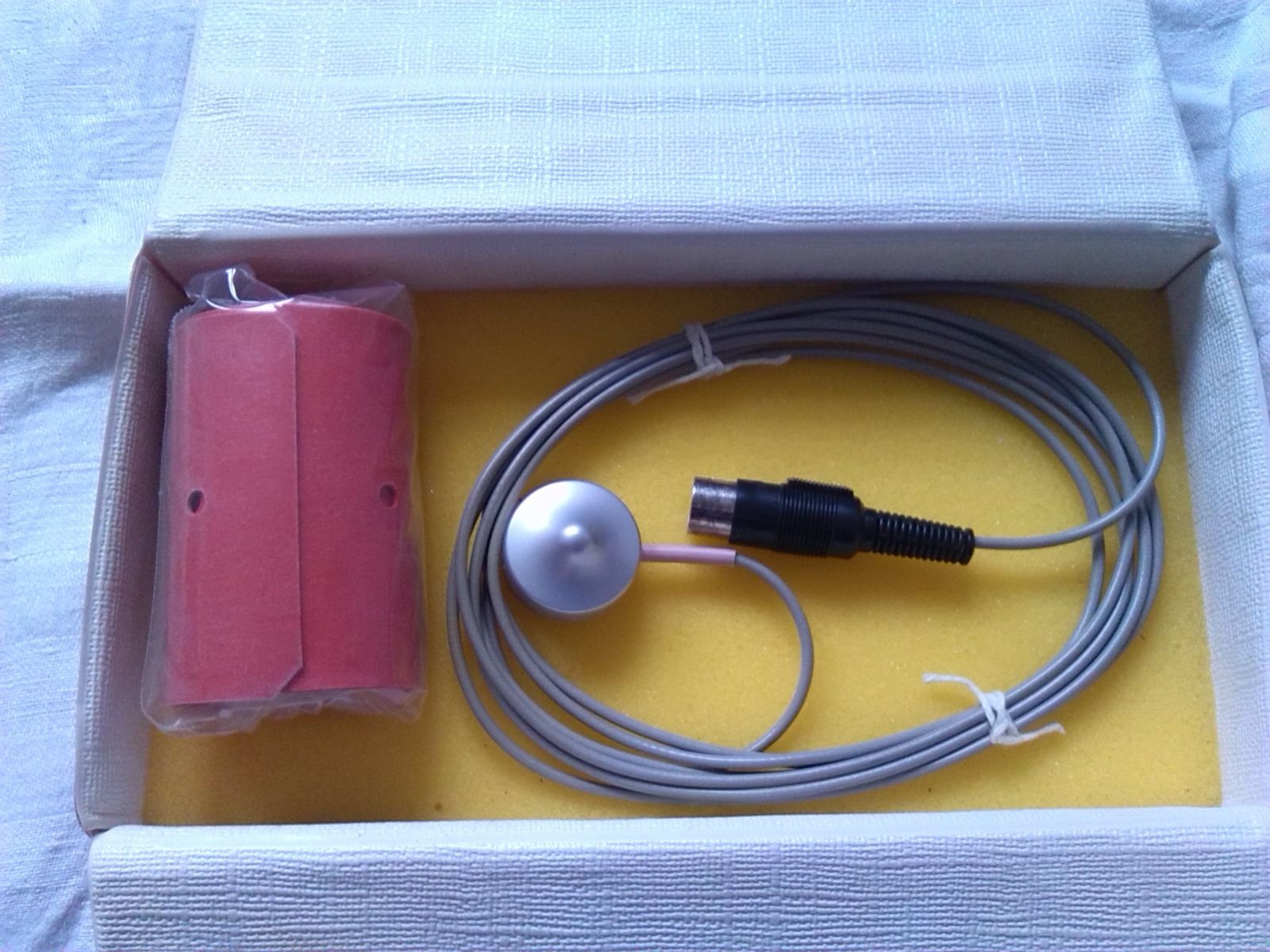
I have an old Medical Heart Sound Cardio Microphone (HM 692) from the former eastern-german company RFT, made in 1978:
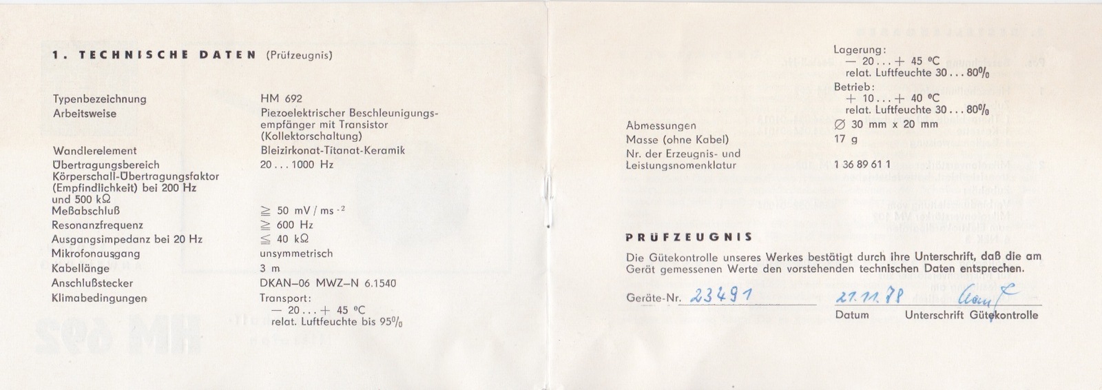
According to the manual it is a "piezoelectric acceleration sensor with transistor (common selector circuit".
What I would like to get working is the microphone together with a modern microphone preamp that has XLR inputs (optionally with 48V Phantom power).
Do you guys have any idea how I get the 6-pin connector of the Old DIN-6 standard connected with the 3-pin of the XLR properly? Any guesses, any tips on that? I do not want to try each pin, because I guess the preamp might burn down…
This is the DIN-6 connector: http://commons.wikimedia.org/wiki/File:DIN-6_fp.svg
This is the XLR male connector: http://upload.wikimedia.org/wikipedia/commons/thumb/8/81/XLR_pinouts.svg/2000px-XLR_pinouts.svg.png
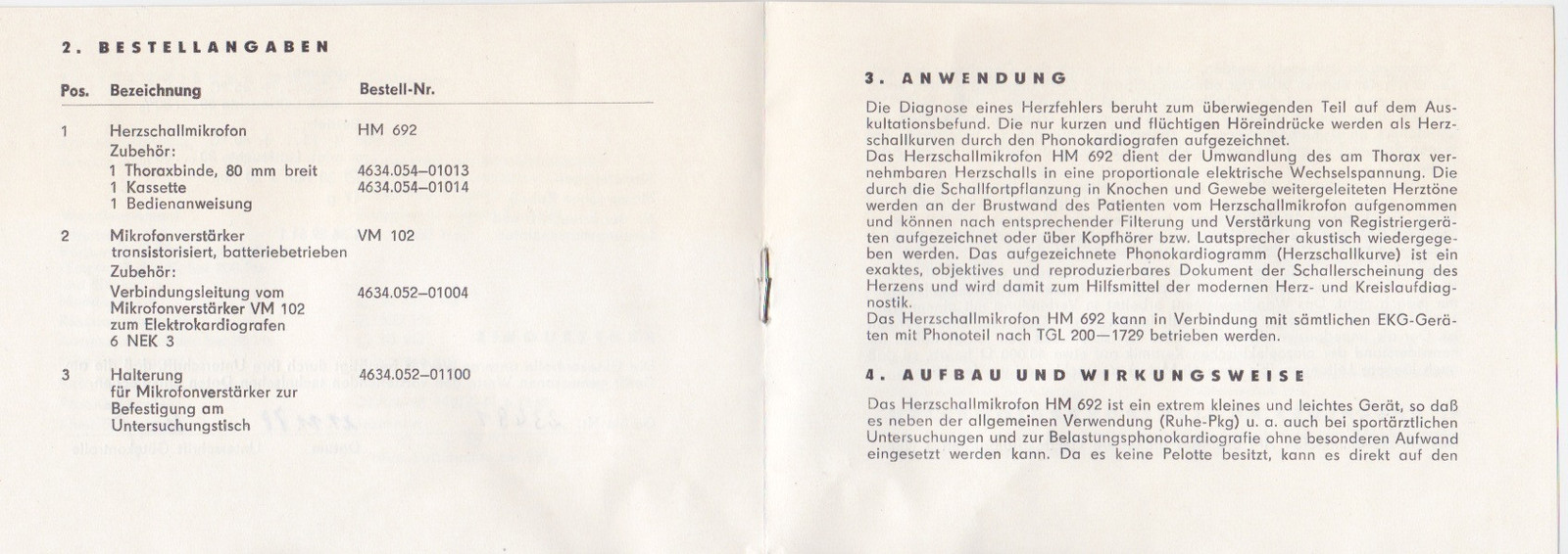
An these are scans from the manual with technical information:
Any help would be highly appreciated!
Kindly
Jimi
Comments
I just experimented a little bit with the mic preamp connected a
I just experimented a little bit with the mic preamp connected and with these pinout combinations:
XLR 3-pin: 1 GND, 2 + (hot), 3 - (return)
DIN 6-pin: 6 GND & 5 + or 6 GND & 3 +
I managed to get a signal with heavy humming with these pinout combinations.
Same applies to XLR pin 3 (-) connected with DIN pin 5 or pin 3.
DIN pins 1, 2 and 4 do not seem to have anything to do with the audio signal.
As the manual states the mic is unsymmetric, so I understand that I only need to allocate two pins with the + (hot) from XLR Pin 2 and the GND from XLR pin 1. Is that correct? XLR Pin 3 - (return) is not needed, or is it the other way around: + and - without GND?
Somehow I do not get a hum-free signal and also I can not hear or record heartbeats, only the sound of my finger knocking against the stethoscope.
Anyone into this?
This is not straightforward, but there is a good chance that it
This is not straightforward, but there is a good chance that it can be achieved without a huge amount of work. You are correct that connecting the microphone directly to 48V phantom power would severely damage it, so DO NOT apply phantom power. In the absence of any more technical information, it will require a little investigation and some careful measurement using a digital multimeter to determine the proper pin connections on the 6-pin DIN plug.
Before I go into technical details, could you tell us (a) whether you are wanting to get it working again for its original purpose (als Herzschallmikrofon) or, if not, for what application, and (2) what is your budget?
I can't imagine, though, that RFT would have used a 6 pin connec
I can't imagine, though, that RFT would have used a 6 pin connector if they could have gotten away with a 3 pin. Having transistors in the circuit means it's active, and requires a power source. I suspect that this device is not phantom powered both because it's a medical device, and it's old. The other pins are used for the power supply, and possibly another signal.
I guess they used a 6-pin connector because it had to be connected with the electrocardiogram directly or with even older cardiograms there was a mic preamp available optionally also – that's what the manual states: The mic preamp available was transistorized/semiconducted.
When I have a signal and I activate the phantom power 48V the signal and the humming go away.
Before I go into technical details, could you tell us (a) whethe
Before I go into technical details, could you tell us (a) whether you are wanting to get it working again for its original purpose (als Herzschallmikrofon) or, if not, for what application, and (2) what is your budget?
I bought and intend to use it for its original purpose: heart beat recording.
My budget is low, I already bought the mic for 60,- and some cables and plugs DIN 6-pin and XLR 3-pin to make my own adapter.
Multimeter is handy.
The only modern stethoscope for recording that I have found on the market is made by 3M Littmann and is not only too expensive, but also has a maximum recording time of 30 sec. and needs bluetooth.
Basically all I want is a stethoscope with microphone to record heart sounds over my mic preamp or without any mic preamp.
I've only just looked at this but looking at the spec. the mic o
I've only just looked at this but looking at the spec. the mic output impedance is 40kOhm and the minimum load impedance is 500kOhm. This looks like the direct output of the piezo device with no pre-amp buffer. Piezo devices are notorious for poor low frequency response if the load impedance is low. I would try an "instrument " input if you have one but these are normally just 1MOhm impedance. Far too many years ago I fitted a peizo mic with a pre-amp that had an input impedance in excess of 10MOhm which actually improved the bass response quite significantly. I would recommend something like this as the frequencies you are looking for are very low. You will also need to be careful with layout and leads to avoid hum pickup at such high impedances. Frankly I'm not surprised that all you get at the moment is just hum!
If it really is "mit transistor" then you will at least need to find out the supply voltage (I'd guess 9-12V shouldn't do any damage) and what the pinout of the DIN plug is.
I'd bet there was a dedicated preamp to convert the output - if
I'd bet there was a dedicated preamp to convert the output - if my poor German is right, then it comes with a transistor collector circuit, which perhaps used to be in the box? I'd bet the actual mic uses an unbalanced high impedance connection, as others have said, that would be a poor match to most modern devices, but in the 70s there were quite a few crystal mics. They work reasonably well into instrument level input, and most line inputs - but the dedicated instrument ones are designed with high impedance pickups in mind. The mics were, however, horrible sounding - very thin and nasty sounding. Speech was announcement quality, and not good at all compared to dynamics and condensers. I'd expect this heart monitor design to concentrate on isolating body sounds - what do you want it for?
I'd take some of your bets Paulears! ;<) I'm fairly certain th
I'd take some of your bets Paulears! ;<) I'm fairly certain that the open collector transistor will be in the mic insert itself as its effectiveness would be reduced by the capacitance of the 3m cable. The spec. does though state that the output is unbalanced. What surprises me is that the transistor is not apparently connected as an emitter follower. When I built a very high impedance buffer circuit (in the late 60's) it was solely to improve the bass response when used with the reel to reel tape recorder it was supplied with. This was to overcome that horrible thin sound, not so much caused by the mic itself, but rather the less than optimum load impedance of ~1MOhm. Whilst not a great mic, it was remarkably better than original and lost much of the horrible tinny sound it previously exhibited. I bet I've still got it if I rummage around!
This unit does use an emitter-follower (Kollectorschaltung) loca
This unit does use an emitter-follower (Kollectorschaltung) located in the microphone body, so it surprises me that the output specification is shown as <= 40KOhm. My feeling is that, given a suitable powering arrangement, it would work perfectly well feeding into a DI input of a pre-amplifier or going via a quality DI-box into an XLR microphone input.
The powering could be as simple as a 9V battery, but I can't be certain which pins to recommend using from the measurements given in the earlier post. That aspect needs a little more investigation, but the point is that the powering and the signal matching to an amplifier input should be treated separately. One has to hope that the unit is still functional after having had 48V PP applied.
Thank you for your answers. I am a visual artist and I want to r
Thank you for your answers.
I am a visual artist and I want to record heart beats from several persons in different situations. It is part of a bigger multimedia project that we would like to exhibit next year.
Now, after I read your comments, I see that I'm having trouble to understand the matters described above, especially when it comes to impendance…
Would anyone of you be interested to investigate the matter further? For that purpose I would send the stethoscope-microphone to you via parcel.
I think it is still working (even after applying 48V Phantom power) because when I attach the pins like described in a few posts earlier, I get not only heavy humming, but also I can hear a sound through the headphones when I (gently) knock with my fingernails against the mic or when I slide over my clothes. So there is definitely some kind of a signal being transmitted. But I can not hear any heartbeats at all, holding it to my chest.
Otherwise, if one of you would be so kind to give me a few instructions (for a dummy) on what to do and what to try, I would love to do so and present my result afterwards.
I tell you, if we can get this working, there are a bunch of old RFT stethoscope mics out there being sold on eBay etc. It could be a cheap way of getting a semi-DIY-stehoscope-microphone setup together.
As I stated above there is currently only one company offering heartbeat recording, but only via bluetooth, expensive software and only clips of 30 seconds, which is not very useful outside of medical diagnosis.
You should be able to carefully open the DIN connector and the w
You should be able to carefully open the DIN connector and the wiring inside might give us a clue depending on how many of the 6 pins are connected. I would suspect that only 3 connections are needed, ground, output and power. It's also possible (but unlikely) that the unit needs a negative supply and similarly uses a second ground connection for the power. Maybe if you could take a photo of the internal connections of the DIN plug we could glean some more clues.
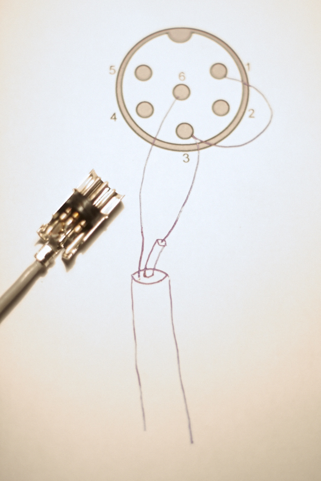
I have cut open the DIN6 plug and cable with the following resul
I have cut open the DIN6 plug and cable with the following results:
The cable has two wires: one inside and one outside, properly isolated from eachother.
The outer wire is connected to pin 6.
The inner wire is connected to pin 3. There is a bridge from pin 3 to pin 1.
See also the photography/sketch attached.
Well that's not what I expected! I cannot see how the emitter f
Well that's not what I expected! I cannot see how the emitter follower is built in to the transducer as the required load impedance is stated to be 500 kOhm. There is no way to power the transistor through the single conductor and maintain that load requirement. It would also explain the output impedance of 40 kOhm. I think what you will need is a very high impedance buffer. I would suggest a load of 10 MOhm to make sure the low frequencies are not impaired. Personally I would go for a JFET source follower or even get a bit of gain using a common source JFET pre-amp. Would you have any idea how to design and build such an pre-amp?
Yes, that does seem odd, and it does not correspond very well wi
Yes, that does seem odd, and it does not correspond very well with the data sheet reproduced earlier. In some ways it makes things simpler as no power supply is required. On the other hand, making sure there is a very high impedance to drive into is not a completely straightforward matter.
I think the best approach may be to use a commercial DI box, treating the microphone as though it were a piezo guitar pickup. The DI box would need to be chosen with its input impedance as a primary parameter, which unfortunately may rule out many of the cheaper passive types. If you were to use an active DI box, the only bit of construction needed would be either to re-wire the DIN plug as a TS jack or to make a short DIN socket to TS jack plug adapter lead.
I agree that a good DI box with at least 1 MOhm input impedance
I agree that a good DI box with at least 1 MOhm input impedance could well suffice. The reason that I harp on about a greater load impedance is that with that ancient crystal mic I had as a schoolboy, I found a very significant improvement in bass response using, IIRC, around 15 or 22 MOhm instead of the 1 MOhm input of the amp I was using. There was room in the mic body for the buffer and battery!
I wonder if we are perhaps applying modern thinking to something
I wonder if we are perhaps applying modern thinking to something quite simple. The housing looks very similar to the standard stethoscope housing. I wonder if the beating of a heart is rather a narrow low frequency thump, and a crystal mic in almost direct connection with the skin produces a very loud output, that simply doesn't need fidelity, just enough volts to supply the connected equipment with what it needs. A bit like a seismograph - you get a faithful output that mimics the real event. The linking of the two pins could simply be a switch for when the plug goes in. It would be possible to simply superimpose a supply voltage, and we are applying audio best practice, and considering quality in determining how impedance and loading will impact on the sound. Maybe they have no need for any of these considerations, and the only requirement is to up the level of a very narrow frequency range, and job done.
Forgetting the modifying of the current device you have for just
Forgetting the modifying of the current device you have for just a moment, and focusing on your original goal, which was to record a human heartbeat...
why wouldn't something like this work?
[[url=http://[/URL]="http://www.youtube…"]View: http://www.youtube…]="http://www.youtube…"]View: http://www.youtube…]
To be clear, I'm not trying to sabotage the part of this thread
To be clear, I'm not trying to sabotage the part of this thread in which modifications are being discussed, which was how to modify the element that Jimi has...
To the contrary, I think it's great when smart minds get together and talk about possibilities. But, since I can't contribute to that end of things, I thought I would at least address the original goal, which was to record heart beats. I think there's likely an easier (and probably better) way to accomplish this task, other than trying to modify an older device... but ...that doesn't mean that I think that this modification shouldn't be discussed... I absolutely do think that it should be talked about, because it's a cool technical concept, and, because we have members like Boswell and MrEase, who are really smart guys.
I'm positive that there is much to be learned, and the only way to learn is to discuss these things.
We all work in a craft where it's absolutely essential to have guys just like Bos and Ease - who not only have the technical knowledge, but who also have the creative mindset to say "hmmm, okay, so, what if...?"
IMHO of course. ;)
d.
paulears, post: 420866, member: 47782 wrote: I wonder if we are
paulears, post: 420866, member: 47782 wrote: I wonder if we are perhaps applying modern thinking to something quite simple.
Well I'm amused by my own thoughts of what colleagues would make of me being accused of "modern thinking"! Sarcasm would abound! ;<)
I think the point is (taking into account later posts too) that the OP has a transducer designed for the purpose, no matter how old it is. The concept is indeed very simple and I have not been thinking in terms of fidelity but rather, as the frequencies involved are low, that it is sensible to preserve the lows by using a high impedance buffer. As Boswell said, a high impedance DI box could be perfectly adequate or even a high impedance "instrument" input on a soundcard.
Rather than trying to reinvent the wheel I think it would be sensible to use the transducer specifically designed for the job and it should not be too difficult to achieve. Whilst it would indeed be possible to superimpose a DC supply voltage, my earlier point was that this could not be achieved on a single conductor given the load impedance required. There is no way to provide sufficient power for a buffer, hence the deduction that the transistor cannot realistically be in the transducer itself. This is again just simple engineering.
BTW, thanks Donny for the kind words. In a way that's why I chose the tag "Mysteries" as I hope to dispel some of the myths that surround the engineering involved in our chosen field.
Thank you for all your answers. It's been a while and I have pro
Thank you for all your answers. It's been a while and I have progressed a little:
I now made myself a simple stethoscope mic with a cheap stethoscope and an simple small speech mic with a tiny preamp. I put the mic in the "sound channel" of the stethoscope and that's it. The results are acceptable. But still I'm not satisfied with the quality.
I will try to get hold of a DI box to go back experimenting on the RFT Herzschallmikrofon.
Currently there is a passive DI box available for me, I'll try that one first and will tell you my results next week.
If that does not work out I will try to get hold of an active DI box.
Jimi du Belle, post: 421815, member: 48550 wrote: Thank you for
Jimi du Belle, post: 421815, member: 48550 wrote: Thank you for all your answers. It's been a while and I have progressed a little..." :
Thank you for being courteous and giving us an update. Not everyone who visits RO seeking help does this ... in fact, hardly any ever do, so thanks for taking the time to do so.
:)
MrEase, post: 420965, member: 27842 wrote: BTW, thanks Donny for the kind words. In a way that's why I chose the tag "Mysteries" as I hope to dispel some of the myths that surround the engineering involved in our chosen field.
We need more guys like you. ;)
Moderating the posts here isn't only about looking for inappropriate behavior - it's also searching for people/posts giving inaccurate information.
When someone posts here on RO, it doesn't just stay here... it goes out to the world; and if someone else may be searching the internet for an answer to a particular problem or scenario, they don't always get accurate information; in fact, there's probably a greater chance of receiving wrong information than there is finding the right information. There's far too much myth and BS floating around out there already about audio and acoustics; and while we can't control what is posted on other sites, we can control it here.
So having cats like you around to give accurate info is absolutely essential. Thanks. ;)
-d.
Back for a thread revival: I have found a german artist recordi
Back for a thread revival:
I have found a german artist recording heart sound with a very special phonokardiograph:

project page: http://ingoguettler.de/kontrapunkt/
It is a metall housing held by two feet. Screwed into the capsule/housing is a red kind of pestle (replaceable). Seems like you put the whole thing on the chest with its two feet and the third red pestle to record the heart sounds…
Does anybody have any idea what it is exactly and where one can get hold of one or DIY?



Hi Jimi, I'm trying to figure out exactly what this unit does.
Hi Jimi,
I'm trying to figure out exactly what this unit does. Unfortunately, Ich spreche kein Deutsch.
I can't imagine, though, that RFT would have used a 6 pin connector if they could have gotten away with a 3 pin. Having transistors in the circuit means it's active, and requires a power source. I suspect that this device is not phantom powered both because it's a medical device, and it's old. The other pins are used for the power supply, and possibly another signal.
I'm afraid it wouldn't accept phantom power without modification to the circuit.
What are you intending to use this for?