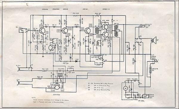
I have two, 212 Craig tape recorders that ran normal, until I used a 9v ac adaptor on both of them, & took out a component that makes it run in ff mode only, no play or rewind. The rewind goes to ff.
I checked my universal ac adaptor, & it was actually giveing it 14v 500ma, when the specs called for the ac adaptor to be 9v 100ma, so obviously took out something like a voltage regulator transistor.
The schematic is included with the instructions, shows 7 transistors in it, but I only see resistors & caps on the small board. (This was manufactured around 1965).
I replaced the belts recently, & was running normal for a few minutes on the ac adaptor, until I figured out, I should have payed attention to the actual dc out put of the adaptor.
Any idea of what to check for first?
Tags
Comments
From the schematic, it appears that the motor runs all the time
From the schematic, it appears that the motor runs all the time the device is switched on and at the same speed (unless there's a plug in the remote control jack). It's therefore likely that the FF-RW-Play tape control is purely mechanical, so, given that the motor is running, I don't understand why the tape motion behaviour would have changed by using an incorrect power supply.
I think your first course of action is to document what appears to work and what does not work when using a 9V battery or (with care) a genuine 9V d.c. external supply, making sure that it has centre -ve on the barrel connector.
It's an amazingly sparse circuit. It reminds me of the stories of "value engineers" equipped with wire cutters going round a prototype product in a factory chopping out components one by one until the product stops working, then soldering that component back and moving on to the next.


I take it they don't work at all anymore? Or have you tried usin
I take it they don't work at all anymore? Or have you tried using a 9V battery to see if some things are still OK?
With the schematic you have there, I would just open it up and start checking each capacitor and transistor with a meter. Preferably one that measures capacitance and has a diode/transistor check position.
Just start at the 9V location and desolder and remove one part at a time and remember or take a photo of how it goes back in. It would only take you less than an hour or so to pull & check all 7 transistors and the 15 or so caps in there.
I would start with the caps. Those are the most likely thing to go. Wouldn't hurt to check all the resistors too but those typically show burn marks or you can smell them when they have burnt up. They're usually OK....you can usually lift one leg of those to measure them accurately enough. You'll probably find the bad parts close to the 9VDC battery, but with something that small and simple I would just go through the whole thing and fix it. Replacing any of the electrolytic caps or parts in there would be cheap and easy to do anyway (it's 50 years old after all) and might improve it in some fashion.
Clean it all up and enjoy a 1965 restored portable 3" RtoR.....LOL
What exactly are you doing with them?
Some experimenting?
Maybe you know this already but just as a heads up thats 9VDC not 9VAC you want for the power.
You can use something that can provide more current over 100mA because the circuit will take what it needs which is at least 100mA but if you use a supply that can only supply say 50mA (less than 100mA) it will not have enough power to run the motor correctly. And it will act like a dead battery.