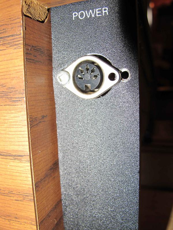
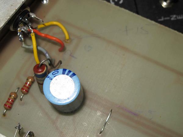
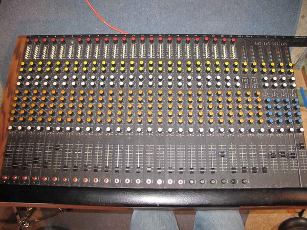
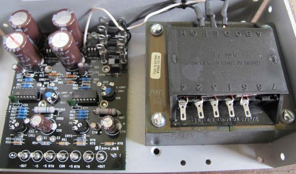
i had an 80's Walker Mixing Console givin to me without a power supply here are some photos - any leads/help?
Comments
stustustudio, post: 389106 wrote: so this one? [[url=http://[/UR
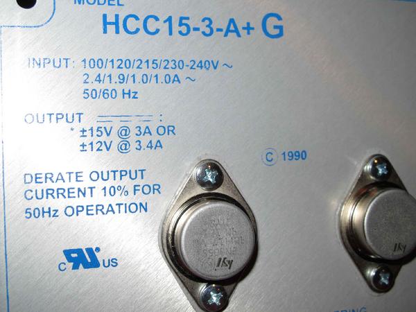
stustustudio, post: 389106 wrote: so this one?
[[url=http://[/URL]="http://www.digikey…"]HCC15-3-A+G SL Power Electronics Manufacture of Condor/Ault Brands | 271-2285-ND | DigiKey[/]="http://www.digikey…"]HCC15-3-A+G SL Power Electronics Manufacture of Condor/Ault Brands | 271-2285-ND | DigiKey[/]
Yep...
The amount of current that flows through the circuitry is depend
The amount of current that flows through the circuitry is dependant on the total load (resistance) not the amount the source supply can provide. A 3A supply might only need to supply 1A to the total load of the board when powered up. It all depends on what the load is.
So the fuses would blow if the total load ends up drawing more than 1.5A from that 3A supply. The power supply still has 1.5A available. If you exceed the power supplies rating (3A) you could end up damaging the power supply which is why it's a good idea to have those fuses. Using the 3A model just gives you extra current capability even though you probably only need a max of 1.5A.
My guesstimate was 1.4A so that still could be the maximum it will ever draw. But it's better to have some "headroom".
But we don't know that for sure. It's all best guess and unknown except for these previous owners clues.
Again you don't even know if there's a short in there or if anything works!
The 3A supply will provide up to 3A to each leg so if the fuse blows then the previous person either had the wrong size fuse or there could be a short somewhere in the supply rails, shorted caps, shorted component etc etc.
That will be the first test....does it power up and do those fuses blow?
Another thing you should do:
Do you have a good VOM meter to check the overall resistance between each supply rail and ground like I mentioned earlier? It wouldn't hurt to do that testing before you go spending money or applying power to a completely unkown unit.
That can tell you a few things. If it's reads a dead short (0 ohms) then you could have a shorted component, bad card or wiring. You'll need to troubleshoot that before you do anything else! So I wouldn't be hooking up any power to it until you know there are no shorts or opens.
If it reads something like 10 ohms then 15V applied would approximately draw 1.5A, so that's pretty close to what we "think it should be. If it reads higher than that like 12 ohms that would be 1.25A. If it reads lower than 10 like 7.5 ohms that would be 2A. If it's 5 ohms that would be 3A and so on.
So doing that would at least give you some more clues. A good quality meter should be able to accurately read those resistance values. Doesn't require any power to do that AND....you can remove everything with just one card at a time and then calculate what one card will draw. Then continue to add cards one at a time taking the resistance measurement. As you add each card the meter should go down. If it ever goes to "zero" than you've found a possible bad board.
Yeah I hear ya...your not crazy...it's fun! I would love to have
Yeah I hear ya...your not crazy...it's fun!
I would love to have that board in front of me. Looks like a really nice board and a bit of mystery...all the more fun!
Of course I have the meters and scopes and tools...so for me it's one of the things as a hobby I enjoy doing.
I guess that's why I'm trying to help you along...I'm just typing what I would do....LOL
And it was free right?....so check it all out before putting bucks into it....that should be the first thing you do....take your time.
It looks like you have most of the thing apart so nows the time to do those checks, clean switches, pots, contacts and look for obvious problems.
Does each board plug into a solid circuit type motherboard at the back there or is there just a wire harness?
It wouldn't hurt to trace out those supply lines and check the connections for shorts or opens.
I like the pictures too...so please take lots and post them!
I'd like to see that spring reverb tank and compressor card....those could be pretty cool vintage features.
Carry on!
with all the strips in, and i ohm test from the -15vdc term to t
with all the strips in, and i ohm test from the -15vdc term to the +15vdc term, and the meter is set to 20K i get a reading of 1.05
everything looks clean in there, no caps bursts, burns or even dust - the modules plug into a socket that goes into a old style PCB board that spans the mixer
stustustudio, post: 389154 wrote: with all the strips in, and i
stustustudio, post: 389154 wrote: with all the strips in, and i ohm test from the -15vdc term to the +15vdc term, and the meter is set to 20K i get a reading of 1.05
everything looks clean in there, no caps bursts, burns or even dust - the modules plug into a socket that goes into a old style PCB board that spans the mixer
Put the meter across GND and +15V and then GND and -15V and see what you get.
Use the lowest scale on the meter you have.
Are you sure that's 339 ohms and 660 ohms?....is it possible it'
Are you sure that's 339 ohms and 660 ohms?....is it possible it's off by a decimal point?...like 33.9 or 3.9?
You can change scales and see if the decimal point changes.
Do you have everything "all" the modules plugged in?
If possible....can you just plug one module into the main socket board and see what that reads?
If that's the correct reading it's means only .044A on the -15 side and .022A on the +15 side.
The only meaningful result you will get from using an electronic
The only meaningful result you will get from using an electronic multimeter on Ohms range from the supply rails to ground is to show there is not a dead short, and you have shown that. I don't see anything that stops you trying the console on +/-15V power.
When you get a PSU and wire it up, you could put the meter on 2A range in series with each of the +15V and -15V power rails in turn to see what current is actually drawn. It could well be in the region of 1.5A in the quiescent state (no signal). This current will increase once you put signals through the unit and out into resistive loads.
stustustudio, post: 389387 wrote: any tips on how i should do th
stustustudio, post: 389387 wrote: any tips on how i should do the terminal/replacement of the DIN connector?
Easy and cheap would be a screw type terminal block or for right now alligator clips just to test it.
Are you going to get a phantom power module as well?
Right now you only have three connections to make, but you would need four if you add the phantom.
If you want something nicer but more expensive, you could find a four pin circular plug and receptacle.
You could probably find one that might go right in the same hole as the DIN.
There are so many choices.
You could also just replace the DIN with a better one.
These would be something nice. You need to buy the plug and the
These would be something nice. You need to buy the plug and the panel receptacle and they have crimp contacts.
You might want something with solder contacts.
These are like $6-7 each, so $12-15 for something like this.
http://www.bulgin.co.uk/PDFs/Cat83_sections/Buccaneer-2010_400_series.pdf
A Switchcraft or Neutrik standard XLR 3 pin could be used and th
A Switchcraft or Neutrik standard XLR 3 pin could be used and they make that same style XLR in 4 pin connectors.
Everything would look like audio connectors then. I would get the 4 pin though so it's different than the regular mic connectors. So that would be an easy replacement. Those would be solder cups too!
Switchcraft also makes "Slim-Line" connectors, but again they have "crimp" style contacts.
Also look at Molex.
Is that a new PSU or used? Isn't there a hookup chart? That pape
Is that a new PSU or used?
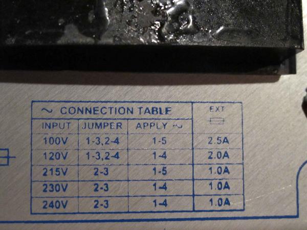
Isn't there a hookup chart?
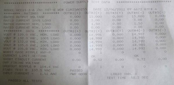
That paper is just a test sheet!
You should have that. Or maybe it's listed on the case.
You should be able to find and download a hookup chart.
Do you have a switch and fuseholder for the AC hookup?
Do you know how to wire that up? There should be a chart to jumper the transformer tabs for 120VAC.
The primary side of the transformer (open tabs) is where your AC cord gets soldered to. But don't forget to fuse the hot side and mount those and a switch. You need to ground the AC cord and connect the green ground wire to the case with grounding type star washers with a nut and bolt or use a self tapping sheet metal screw big enough to bite into the metal of the chassis somewhere. make sure it makes a good connection to ground.
Looks like Out2 is the +15VDC
And Out4 is the -15VDC
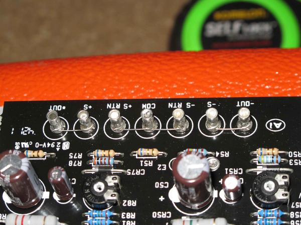
COM would be the GND
Ok your starting to scare me now...?? LOL The AC cord has a blk
Ok your starting to scare me now...?? LOL
The AC cord has a blk wire a white wire and a green wire.
Blk is hot
Wht is neutral
Grn is ground
You need a SPST power switch rated for 120VAC at least 5A and a fuse holder. Not sure if that should be 2A or 3A slo-blow in series with the AC hot wire. The input chart says 2A so that would be probably the right size.
If you don't mount those to something they will just be hanging out in mid air??? and they'll touch something and if you're touching anything metal it will shock and possibly kill you....so yeah.
Do you know how to wire a SPST switch? Don't be wiring it across the hot and neutral or anything like that. It goes "in series" with the hot only. See schematic posted earlier.
The hot side after the switch and fuse will go to tab #1. Again see the earlier power supply schematic.
You have to solder a jumper wire across tab #1 and 3 and another jumper wire across tab #2 and 4.
The neutral (white) goes directly to #4 tab. So AC goes on 1 and 4
The green ground HAS to be attached to the chassis of the unit like I stated earlier for shock/safety.
Make sure all of the AC side stuff is insulated and not touching anything except the connections.
Leave the DC output until you get that put together and working. Then you can put you meter on COM and +out and you should measure +15VDC.
Do the same on the COM and -out and you should read -15VDC.
Then you can wire the PSU to the mixer.
If your not comfortable doing all this you should find an electrician or tech to help.
You don't want to burn you place down or hurt yourself if you don't understand this stuff....It is dangerous.
stustustudio, post: 389423 wrote: a mounted fuse?, what amperage
stustustudio, post: 389423 wrote: a mounted fuse?, what amperage? between the transformer and the wall? the three prong has two "hot" wires, which one gets "fused"?
djmukilteo, post: 389425 wrote: Ok your starting to scare me now...?? LOL
...
If your not comfortable doing all this you should find an electrician or tech to help.
You don't want to burn you place down or hurt yourself if you don't understand this stuff....It is dangerous.
I second both of those sentiments. A) Your question scares me too, and B) you're getting into territory with REAL danger.
Please have someone a little more familiar with high-voltage at least supervise and inspect this fuse project before you plug it in. Do you know why there's a fuse in the first place?.. to prevent a fire. Wouldn't it be nice to sleep without wondering if you did everything right, and if/when it was going to burst into flames?
dj and Boswell have given excellent advice and guided you to this point, but it might be wise to have an electrician give it a 60 second inspection.
It's always sketchy trying to explain electrical stuff to someon
It's always sketchy trying to explain electrical stuff to someone on a forum when you don't know or have any idea of their experience.
Electrical stuff isn't like drilling a hole in something or cutting or painting something.
It can be dangerous especially with 120VAC and exposed circuits. Never make connections or solder on any of that when it's plugged in. Always make sure it's unplugged first.
Never touch any exposed conductors or components if the power is on. Always use insulated handle tools and meter probes when testing or checking for voltage and current on a live circuit.
I would hate to find out you or someone around you got hurt doing this yourself without a healthy understanding of the cautions.
Going to your local tech place is a good idea.
I had a good friend of mine call me on the phone one day and ask
I had a good friend of mine call me on the phone one day and ask me to come over right away and help him with his electric hot water heater.
He sounded a little upset and frazzled and I asked him what was going on and what the problem was.
He reluctantly told me his electrical water heater went out. He decided to disconnect it and get a new one. He had opened the cover on the electrical box behind the tank and removed the wire nuts to remove the flex conduit to the heater tank and then left the wire in the box with bare ends hanging out of the box.
He hadn't shut the circuit beaker off at the panel.
He told me there was water on the floor from the leaking tank.
He said he had reached around the back of the tank to move it and leaned forward touching his FOREHEAD to the bare hot wire hanging out of that box.
FLASH!
It burned a spot on his forehead, threw him backwards across the laundry room hitting his arm, leg and back on the opposite wall and shelves! Luckily it threw him and his head away from that bare wire!...
He was lucky he wasn't dead on the floor!!!
He was standing in the water!!! He was lucky the muscle contraction didn't cause him to clamp onto the wire like can happen when you touch bare wiring with your hand. He would have been dead in the water as they say!
He was bruised and sore and had a major headache!
After he told me this I was just speechless....at the time I called him every stupid cuss idiot word I could think of and then we laughed about it and I went over shut the breaker off, cleaned up the mess and put in his new heaters safe and sound. He wouldn't even go back in the room....
Something he will never forget and something I never let him forget about especially how lucky he was!
In later years that same friend lost the top portion his finger when a chipper sucked his glove into the blades. He pulled his hand away just in the nick of time. He was lucky again!....this time however minus part of one finger.
A dumb electrician is a dead electrician...that's why there are no dumb electricians. Or they're just plain dangerous!
And old electricians are very smart people....LOL
I do not like working with gas (especially under pressure) and electricity in the same object or area....it really bothers me...alot...they don't mix well.
But sometimes it has to be done....pucker up!
I think those S terminals are "sense" posts for over current det
I think those S terminals are "sense" posts for over current detection. So nothing you need to change.
Now that you have your AC done, just plug it in flip the switch and use your voltmeter to test the outputs.
COM, +OUT and -OUT. Those are your three wires going to the mixer.
If all is good and no smoke or sparks then you can hook it up to the mixer.
powered it up no smoke no smell no buzzes or noise - ran a stere
powered it up no smoke no smell no buzzes or noise - ran a stereo mix through two channels and direct out (on the same strip) to a pro playback amp. everything on the channels work - the EQ is dynamite! noticed that there is no stereo main out on the board!? just 4 main outs out of the bus channels - i guess i have to figure out how the board works now. try those compressers and reverb. gonna pot spray and alcohol/toothbrush everything first (didn't do that yet - ooops)
Can't tell from the photos but I think you just assign any chann
Can't tell from the photos but I think you just assign any channel to Bus 1 and any other channel to Bus 2.
Pan those to taste and viola' stereo. You have 4 of them, so 4 mono or 2 stereo....24 ch x 4 bus.
Are you using powered monitors?...or are you using a receiver/amp with speakers?
It looks like the reverb/comp strip is also assignable to the 4 bus?
But I can't tell from any of the photos if you can use them on individual channels?
Also I noticed in one of the partial photos it has balanced XLR connectors on the back. Does it have any transformers in it?
If you get a chance take a close up photo of the mono channels, the bus section and the comp/reverb.
And a full one of the back...that would be nice too!
Anyway I'm sure you'll figure it out.



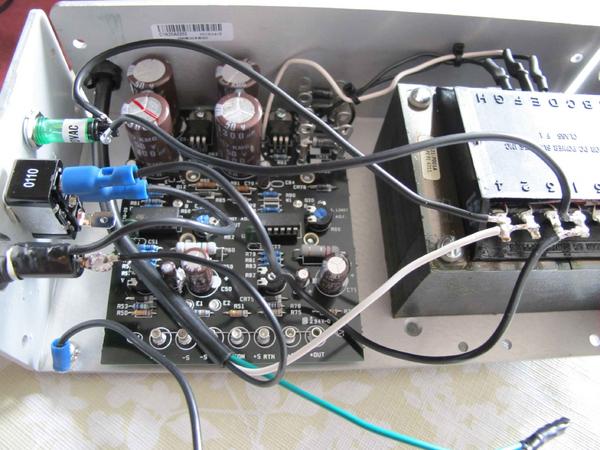
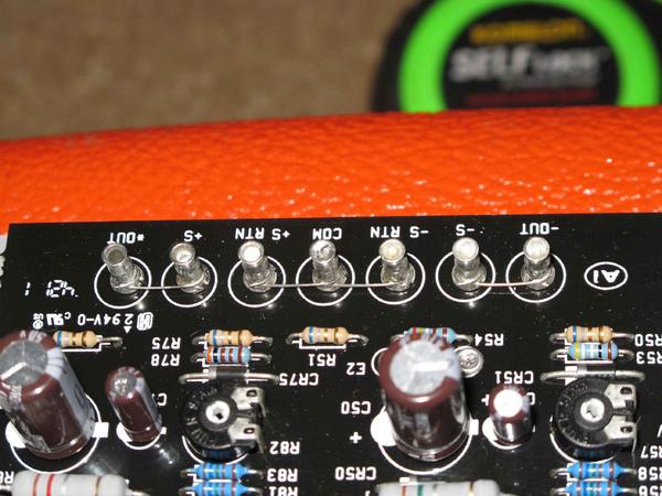
so this one? [[url=http://[/URL]="http://www.digikey.ca/product-
so this one?
[[url=http://[/URL]="http://www.digikey…"]HCC15-3-A+G SL Power Electronics Manufacture of Condor/Ault Brands | 271-2285-ND | DigiKey[/]="http://www.digikey…"]HCC15-3-A+G SL Power Electronics Manufacture of Condor/Ault Brands | 271-2285-ND | DigiKey[/]