I would like to analyze analog circuits by sending a stimulus through it and then recording the output, changing the circuit slightly and then running the test again to produce two *almost* identical .wav files that can then be compared sample-for-sample.
Currently I can use a "Spot Frequency Resp." feature of the DSSF3 program on Windows to generate the stimulus and then the "Recording" utility of the same program to record the output. This is through an M-Audio Fast Track USB. I can then test the same unmodified circuit one test right after the other just as a "control". They should be identical minus noise because noise in an analog circuit is random from one run to the next. I then wrote a C program using libsndfile to open the two 48kHz 24bit .wav files, subtract them sample-by-sample and then write a third .wav file representing the sample-by-sample difference of the two recordings. The DSSF3 Recording utility automatically starts when the Spot Frequency Resp. starts but this does not quite work ...
The problem is that the sample delay is not fixed. It can vary by several milliseconds. I need the sample delay to be fixed at exactly some number samples. I don't care if it's 10 or 1000, it just needs to be exactly the same every time. Actually it really needs to be a fixed number of clock cycles so that there's almost no time shift at all. Otherwise, even if the input sample was synchronized with the same output sample from one run to the next, if the time was off by 1/2 of the sample period, I think the resulting difference .wav would show differences at high frequencies that are just interference and do not actually represent differences in the circuit. I believe this because if I manually re-align the samples using WavePad, it still shows significant differences between the control files. Meaning the two files are out of phase by a fraction of the sample period. So ideally the ADC should start collecting samples at a certain fixed number of clock cycles after the DAC starts writing samples. Is this possible?
Can anyone recommend software / hardware or some combination thereof so that I can digitally transmit a stimulus through an analog circuit and then record it's output after a precise fixed and completely reproducible number of clock cycles?
Obviously I'm just doing this for fun so hopefully there is a solution that does not break the bank. The solution doesn't have to be professional - I would be perfectly ok with using some eval board for a codec and writing some dsPIC code or some such to drive it. Of course the ideal solution would be if there was some software that could just get my little Fast Track to do the job.
Comments


You have two problems: (1) the synchronization of the sampling,
You have two problems: (1) the synchronization of the sampling, and (2) the belief that you will get what you need out of the test.
PC-based analysis programs of this type are generally not sample-accurate, as they have to deal in the shape of a response rather than the numerical values of successive samples. When I have needed to take samples in this way (usually for non-audio purposes), I usually use an Alesis HD24XR hard disk recorder, which by design is sample-accurate. I can record the stimulus waveforms on one or more tracks then play the stimulus while filling up the rest of the 24 tracks with responses, one at a time if necessary, knowing that the output waveform and input sampling instants are precisely the same each time I play the stimulus.
As for the second point, sample-accurate recordings are not necessary in order to analyse circuits. Waveforms with known repeatable characteristics are necessary (e.g. pseudo-random noise), but the position of the samples within the output waveform does not have to be the same each time, as they go through a reconstruction filter that removes all traces of the sample instants. As long as you time the stimulus from the reconstructed waveform and not from the samples that went into making up the waveform, you lose no information.
Using sample-accurate replay and recording is a shortcut that appears to avoid more difficult timing methods, but you have to be very sure that doing it that way does not mask effects that you would otherwise see when timing from the waveforms themselves.

Gette, post: 406353 wrote: Before I would recommend anything, I
Gette, post: 406353 wrote: Before I would recommend anything, I would need a little more background on what you are trying to accomplish in the end. more so "purpose" of the test procedure. Knowing what your end goal is would help to narrow the field of options.
A lot of the circuits I work with are highly non-linear. For example, right now I'm toying around with overdriving a "Deacy amp" which is a very old push-pull amp with interstage and output transformers. I want to see what if any effect a real speaker load has compared to a simple resistor load. And I want to know if the transformers project the load of the speaker back into the preamp. Or if I use transistors with wildly different hfe in the push-pull output, what affect does that have on the asymmetry of the output. If I use a slow 1MHz Germanium transistor somewhere compared to "fast" one, I might expect to see bumps that indicate that there is in fact a difference in rise time.
I did find a program called Audio DiffMaker that looks like it does *exactly* what I want. [snip bad conclusion about DiffMaker]
EDIT: After some experimentation it seems DiffMaker actually works quite well. After writing a C program to very carefully craft a stimulus file and unchecking the gain adjustment setting, it seems DiffMaker is reliably producing good difference files.

bouldersound, post: 406358 wrote: Split the stimulus signal and
bouldersound, post: 406358 wrote: Split the stimulus signal and loop one copy directly to its own channel on your audio interface. Record the loop back and the circuit-altered signals to separate tracks and compare.
I'm not trying to compute the difference between the input and the output. I am trying to compute the difference of the output before with the output after making a change to the device being tested. So I play the stimulus and record the output. Then I make a change to the device like change a transistor and play the stimulus again and save that output to a second file. Then when I compare the two output files the difference should be just the effects of the transistor that was changed (plus noise because it is not part of the stimulus).
Would it not be simpler to simply graph the response curves of e
Would it not be simpler to simply graph the response curves of each modification? IE AP System one? You can get a good working AP unit, albeit a little older, but none-the-less a very reliable and more importantly accurate unit in which to compare minuet differences between mods. Although, I am sure you are trying to hear a deference and/or compare visually the deferent recordings. However to truly understand how each modification affects the outcome, you need test equipment that is not only industry standard but can in fact record and present you with a graphical measurement.
ioplex, post: 406361 wrote: I'm not trying to compute the differ
ioplex, post: 406361 wrote: I'm not trying to compute the difference between the input and the output. I am trying to compute the difference of the output before with the output after making a change to the device being tested. So I play the stimulus and record the output. Then I make a change to the device like change a transistor and play the stimulus again and save that output to a second file. Then when I compare the two output files the difference should be just the effects of the transistor that was changed (plus noise because it is not part of the stimulus).
I know I can record the output of my DAW back to the input twice and the two versions are sample accurate to each other. If I invert one they null perfectly. That should satisfy your requirements. Play stimulus from track 1, record original state of circuit on track 2, the modified circuit on track 3 and you should have sample accurate aligned recordings of the two states.
It appears that DiffMaker may do what I want after all. After re
It appears that DiffMaker may do what I want after all. After realizing that I was using a bad stimulus, I have managed to get good difference files.
The following graphic shows the difference in output of my "Deacy amp" circuit with a 4 ohm resistor load versus a 4 ohm speaker load. The left side shows the control which is just difference between two runs of the speaker load. The right side is the difference between the resistor and speaker. There isn't a dramatic difference. But a speaker load does clearly make a difference.
So it seems I have basically solved this problem at this point. After making some disparaging remarks about DiffMaker (edited out above) it seems the problem was the user. I was using a program to generate the stimulus. That was a bad idea. The stimulus was not consistent. So I generated a .wav with a sequence of 10 tone pulses of different frequencies with a 75% duty cycle and frequencies spaced logarithmically so that you can view the pulses as in the frequency domain and not just the time domain. Then I used DiffMaker to play the stimulus while recording the ouput instead of a separate program. Anyway, the important thing was that the sine waves and 0's were digitally perfect so that the stimulus was exactly the same each time.
Attached files 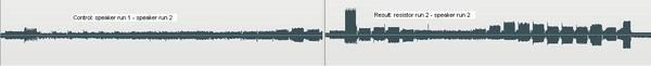
Before I would recommend anything, I would need a little more ba
Before I would recommend anything, I would need a little more background on what you are trying to accomplish in the end. more so "purpose" of the test procedure. Knowing what your end goal is would help to narrow the field of options.